Chapter 1 Overview
Front and Rear Panel Descriptions
1-8
Cisco Redundant Power System Hardware Installation Guide
OL-3654-01
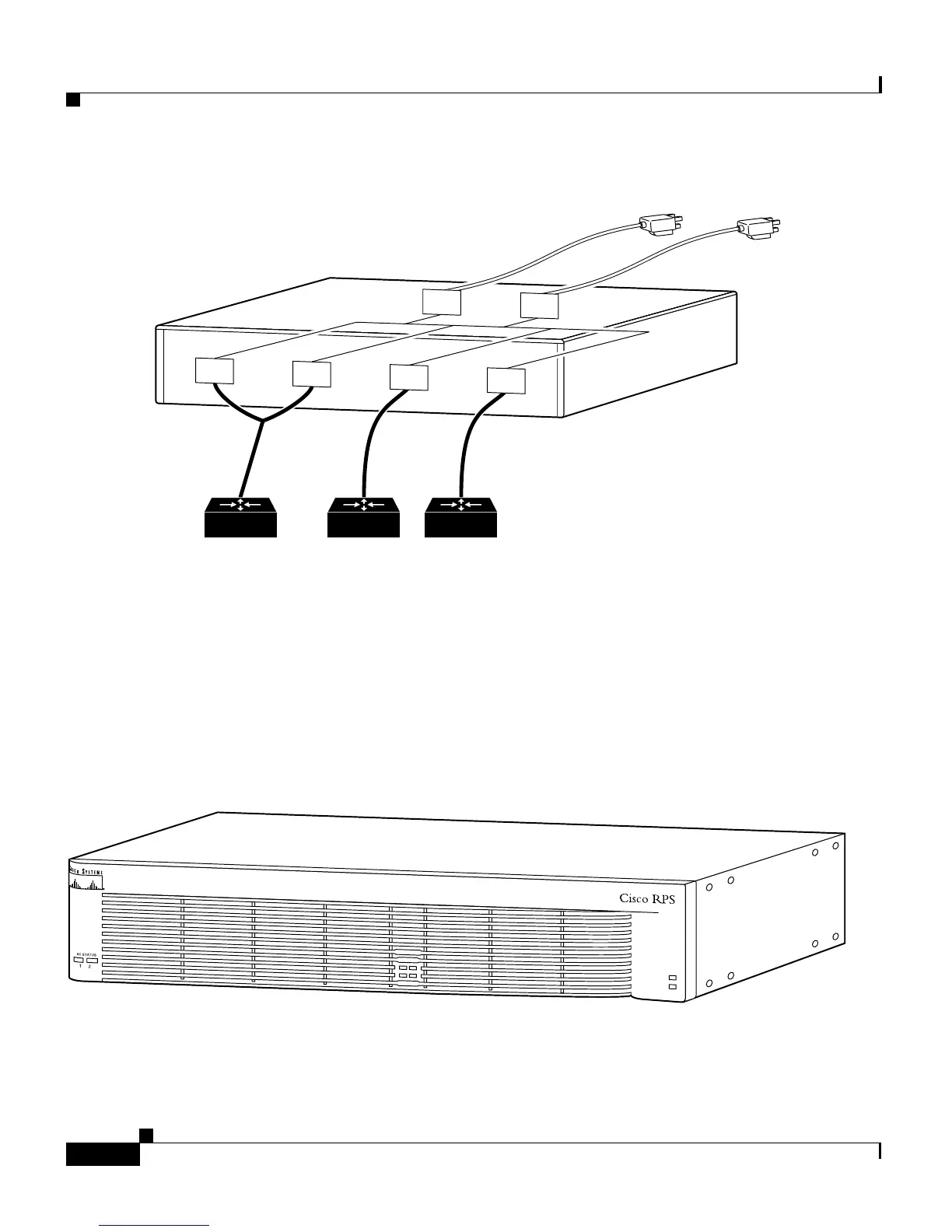
Figure 1-4 Mixed Configuration
Front and Rear Panel Descriptions
The LEDs on the Cisco RPS front panel show the Cisco RPS operational status.
Figure 1-5 shows the front panel of the Cisco RPS.
Figure 1-5 Cisco RPS Front Panel
Quasi-RedundantFully redundant
AC input
AC
AC
DC
DC
Cisco RPS
11681
DC
DC
DC output
H9588
DC STATUS
12
3
4
FAN
TEM
P