1-9
Cisco Redundant Power System Hardware Installation Guide
OL-3654-01
Chapter 1 Overview
Front and Rear Panel Descriptions
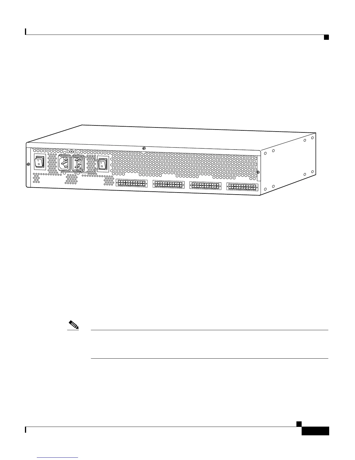
The Cisco RPS rear panel has two AC power connectors, each with an on/off
switch, and four DC connectors for connecting to devices. Figure 1-6 shows the
rear panel. See Chapter 3, “Connection Requirements,” for information about
required cables and connectors.
Figure 1-6 Cisco RPS Rear Panel
LEDs
The LEDs on the front panel of the Cisco RPS display the current operating
condition of the Cisco RPS:
• AC STATUS LEDs—Two on the left side of the front panel.
• DC STATUS LEDs—Four on the center of the front panel.
• FAN and TEMP LEDs—Both on the right side of the front panel.
When the Cisco RPS is working properly, all LEDs on its front panel are solid
green.
Note Some external devices also include LEDs that show the operating condition of the
Cisco RPS. Refer to the installation guide that accompanied the device for
detailed information about the device LEDs.
H9589
AC INPUT 1
100-200 V~ 50/60 Hz
10-5 A 1000 W
AC INPUT 2
100-200 V~ 50/60 Hz
10-5 A 1000 W
DC OUTPUT 1
DC OUTPUT 2
DC OUTPUT 3
DC OUTPUT 4