Chapter 4 Connecting the Cisco RPS
Connecting Switches
4-6
Cisco Redundant Power System Hardware Installation Guide
OL-3654-01
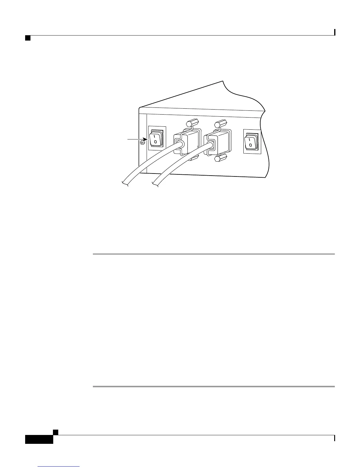
Figure 4-5 Powering Up the Cisco RPS
The Cisco RPS provides power in 10 to 15 seconds. The Cisco RPS is working
properly when all its front-panel LEDs are solid green. If the external device does not
power up, refer to Chapter 5, “Troubleshooting the Cisco RPS.”
Connecting Switches
The Catalyst 1900 series and Catalyst 2820 series switches and the Catalyst 2900
series and Catalyst 3500 series XL switches can use:
• One-to-one cable for quasi-redundancy
or
• One-to-one cable with the switch AC power cable connected for redundancy
with reboot (not recommended)
To connect switches to the Cisco RPS, perform these steps:
Step 1 Disconnect the AC power cord on the switch.
29091
Power switch