Chapter 1 Overview
Front and Rear Panel Descriptions
1-10
Cisco Redundant Power System Hardware Installation Guide
OL-3654-01
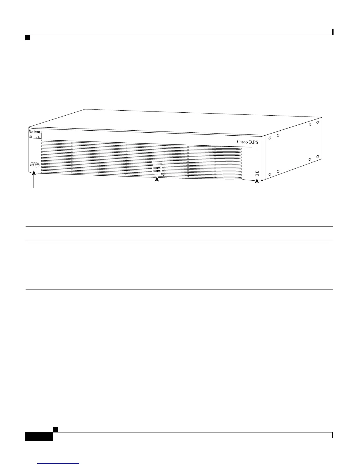
Figure 1-7 shows the Cisco RPS front panel LEDs, and Table 1-2 explains the
meaning of the colors.
Figure 1-7 Cisco RPS LEDs
Table 1-2 LED Descriptions
LED Name Color/State Description
AC STATUS Off AC power is not being supplied to the Cisco RPS, or it is switched off.
Amber AC power is being supplied to the Cisco RPS, but the designated
AC-input power module has failed.
Green The AC-input power module is on and operating correctly.
DC STATUS
Off
Note The DC status LEDs are numbered to correspond to the
DC-output connectors on the Cisco RPS rear panel.
The DC output is powered down at the external device, AC power is not
being supplied to the Cisco RPS, or there is no output cable attached to
the DC output module.
DC STATUS
12
3
4
H9629
AC status LEDs
DC status LEDs
Fan and temp LEDs
FA
N
TEM
P