9-9
Cisco SCE8000 Installation and Configuration Guide, Rel 3.1.7
OL-16478-03
Chapter 9 Removal and Replacement Procedures
Removing and Replacing the Power Supply
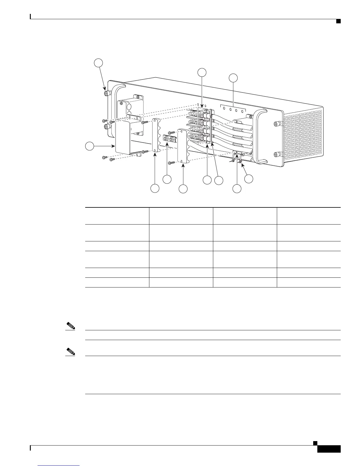
Figure 9-5 DC-Input Front Panel for 2700-W DC-Input Power Supply
Step 6
Attach the appropriate lugs to the DC-input wires and ground wire. The wires should be sized according
to local and national installation requirements. Use only copper wire. The maximum width of a lug is
0.600 inch (15.2 mm).
Note Use fine-stranded copper conductors rated for 90-degrees Celsius for North American installations.
Note The power supply terminal block lug opening width is 0.62 inch (15.8 mm). The terminal posts are
centered 0.625 inches (15.88 mm) apart and are 1/4-20 threaded. We recommend that you use an
appropriately sized industry standard 2-hole, standard barrel compression lug. The power supply ground
studs, located below the terminal block, are also threaded 1/4-20 and require two 1/4-inch split-ring
washers and two 1/4-20 hex nuts.
1 Captive installation
screw
7 Cable holder cover
2 DC power cable
terminal block
8 Cable holder
3 Status LEDs 9 Tie-wrap
4 DC power cable
terminal block cover
10 Cable holder
5 Cable holder cover 11 Tie-wrap
6 Ground
132219
PWR-2700-DC/4
-VE-1
-VE-1
-VE-2
-VE-2
IN
PU
T
1
O
K
48V
-60
V
=40A
IN
P
U
T2
O
K
48
V-60V
=40A
FA
N
O
K
OU
T
PU
T
FA
I
L
ALL FASTENERS MUST B
E F
ULL
Y ENG
AGED
PR
IO
R TO
O
PERA
TING THE PO
W
ER SUPPL
Y
3
2
6
4
10
1
8
5
7
11
9

 Loading...


