4-18
Cisco SCE8000 Installation and Configuration Guide, Rel 3.1.7
OL-16478-03
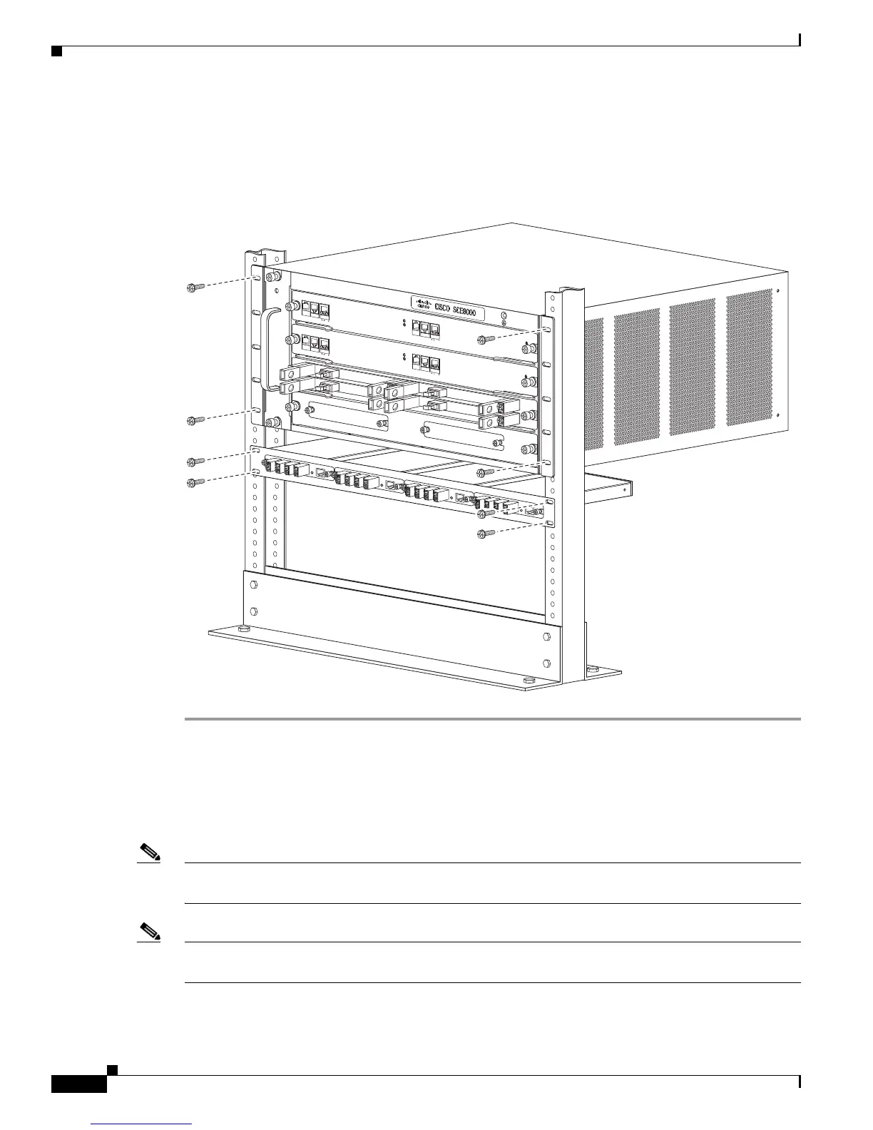
Chapter 4 Installing the Cisco SCE8000 Chassis
Connecting the System Ground
Step 2 Remove the module filler plate covering the subslot in the mounting panel by loosening the two screws.
Step 3 Carefully insert the optical bypass module into the subslot (there are no guide rails) and tighten the
captive screws on either side of the module.
Figure 4-15 Optical Bypass Modules in External Mounting Panel
Connecting the System Ground
This section describes how to connect a system (earth) ground to the Cisco SCE8000 chassis.
Note You must connect the system ground on both AC- and DC-powered systems to an earth ground if this
equipment is installed in a US or European Central Office.
Note For DC-powered systems, the system ground is also the power supply ground. The DC ground must be
installed with a permanent connection to an earth ground according to NEC guidelines.
270994
FA
N
S
T
AT
U
S
SC
M
1
S
C
M
2
SIP
3
4
SC
E80
00-F
AN
SY
S
T
E
M
PO
W
E
R
OP
TI
C
A
L
B
YP
A
S
S
S
TATU
S
A
UX
P
O
R
T
2
L
IN
K
A
C
TI
VE
MA
STE
R
S
C
E
8
0
0
0
E
X
T
E
N
DE
D
S
E
R
V
I
C
E
C
O
N
T
R
OL
M
O
D
U
L
E
O
P
T
ICAL
BYPASS
O
PT
I
C
AL
BYPASS
CO
N
SO
L
E
1
0
1
0
0
1
0
00
L
IN
K
AC
TI
VE
PORT 1
S
Y
S
T
E
M
P
O
W
ER
OP
TI
C
A
L
B
Y
P
A
S
S
S
TA
TU
S
A
U
X
POR
T
2
10
10
0
10
0
0
L
IN
K
A
C
T
I
V
E
M
A
S
TE
R
S
C
E
8
0
00
E
X
T
E
N
D
E
D
S
ER
V
I
C
E
C
ON
T
R
O
L
M
O
D
U
L
E
S
CE80
0
0
-S
C
M-E
S
CE8
0
0
0
-S
C
M-
E
S
CE8
0
0
0
-S
I
P
CO
N
SOLE
1
0
1
0
0
1
0
00
LI
N
K
AC
TI
VE
POR
T
1
O
P
T
ICAL
B
YP
A
SS
OPTICA
L
B
YP
A
S
S
S
TA
T
U
S
AC
TIV
E/LIN
K
SP
A
-1X1
0G
E
-
L
-
V
2
ST
A
TUS
A
C
T
IVE
/
L
INK
SP
A
-1X
1
0G
E
-
L
-
V
2
S
T
A
T
U
S
A
C
T
IVE
/LINK
S
P
A
-1X10
GE
-L
-V
2
S
T
A
T
U
S
AC
T
I
VE
/
LI
N
K
S
P
A
-1X10
GE
-L
-
V
2
1
0
10
0
1
0
0
0

 Loading...


