2-2
Cisco SCE8000 Installation and Configuration Guide, Rel 3.1.7
OL-16478-03
Chapter 2 Introduction to the Cisco SCE8000 Platform
Service Control Module (SCE8000-SCM-E)
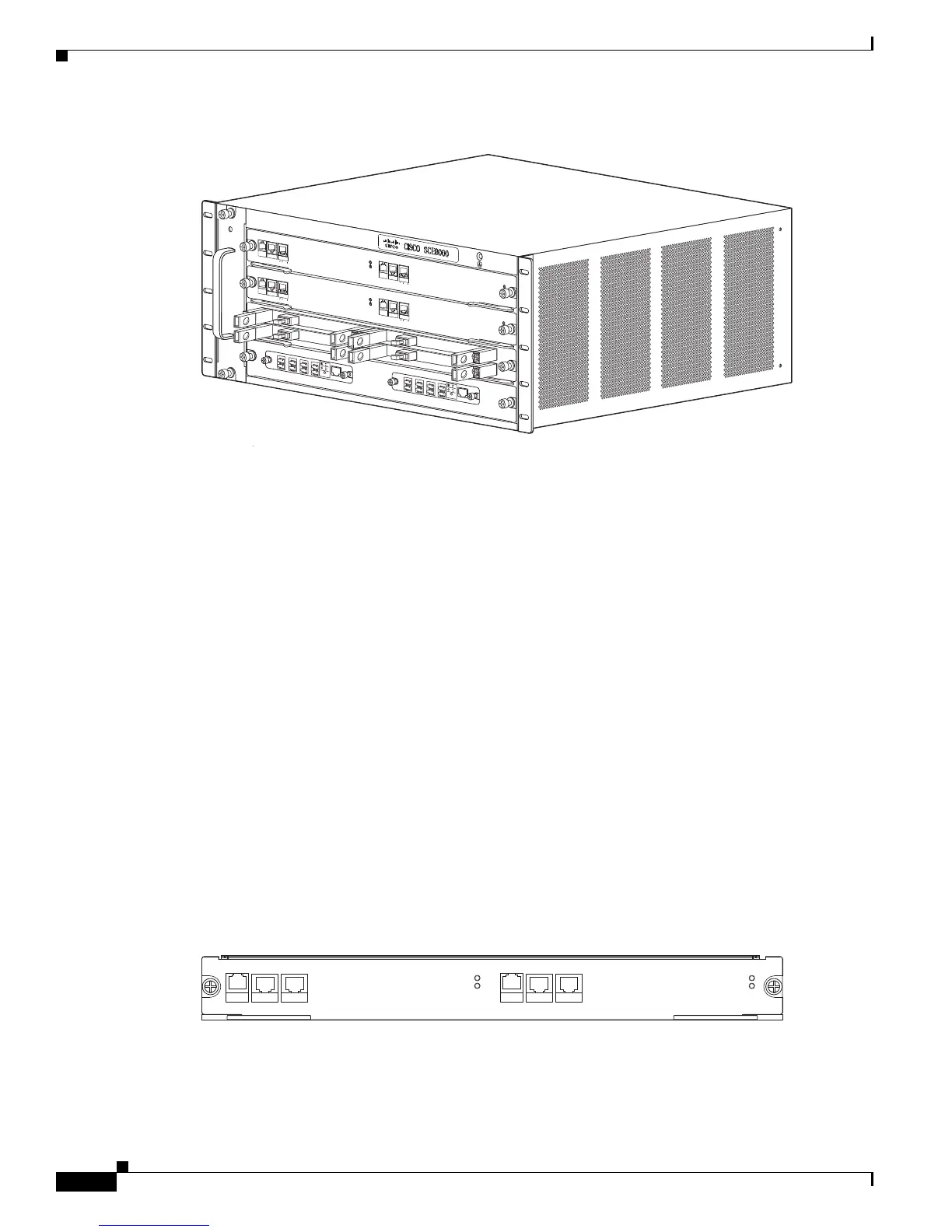
Figure 2-1 Cisco SCE8000 Platform
The Cisco SCE8000 supports the following network insertion models:
• single appliance (inline)
• single appliance (receive-only)
• cascade configuration
• MGSCP configuration
The Cisco SCE8000 platform is a 4-slot chassis hosting the following modules:
• One or two Service Control Modules (SCE8000-SCM-E) that each contain special purpose fast path
chipset, traffic processors and control processor.
• One SPA Interface Processor card (SCE8000-SIP) that holds up to four SPA 10GBE interface
modules.
• One optional optical bypass module hosting panel that holds up to two optical bypass modules.
In addition, the Cisco SCE8000 chassis contains two power supply modules in a 1+1 configuration, as
well as a fan tray module.
Service Control Module (SCE8000-SCM-E)
The Cisco SCE8000 contains one or two SCE8000-SCMs located in slots#1 and #2 (the top two slots).
The Service Control module contains ports and LEDs as shown in the following figure and tables.
Figure 2-2 SCE8000-SCM-E
.
270543
FA
N
STATUS
S
C
M
1
S
C
M
2
S
IP
3
4
SC
E
8
00
0-
FA
N
S
Y
STEM
POW
E
R
O
P
T
IC
A
L
BY
PAS
S
S
T
A
T
U
S
A
U
X
P
ORT
2
L
IN
K
A
C
T
I
V
E
M
A
ST
ER
S
C
E
8
000
E
X
T
E
N
DE
D
SE
R
V
IC
E
C
ON
T
R
O
L
M
O
DU
L
E
O
PT
I
C
AL
BY
P
ASS
O
PT
IC
AL
B
YPAS
S
C
O
N
S
OLE
1
0
1
0
0
100
0
L
IN
K
A
C
TI
V
E
PO
R
T1
A
C
A
B
C
D
B
D
ST
ATU
S
CTR
L
O
P
B
-
S
C
E
8
K
-
M
M
O
P
T
I
C
AL
B
Y
P
A
S
S
1
T
X
R
X
TX
R
X
TX
R
X
TX
R
X
A
C
A
B
C
D
B
D
S
TA
TU
S
CT
RL
O
PB
-
SCE
8
K
-M
M
O
PT
I
C
A
L
B
YPA
S
S
2
T
X
RX
T
X
R
X
T
X
RX
TX
RX
S
Y
ST
E
M
P
O
W
E
R
O
P
T
IC
A
L
BY
PAS
S
S
T
A
T
U
S
AUX
POR
T
2
10
100
10
0
0
LINK
A
C
TI
VE
M
A
ST
ER
S
C
E
8
000
E
X
T
E
N
DE
D
SE
RV
I
C
E
C
O
NT
R
O
L
M
O
DU
L
E
S
CE80
0
0
-
S
C
M-
E
S
C
E80
0
0
-
S
C
M-
E
SC
E
8
0
00-
S
IP
C
O
N
S
O
L
E
10
10
0
100
0
L
IN
K
A
C
TI
V
E
POR
T
1
O
PT
I
C
AL
BY
P
ASS
O
P
TI
CAL
BY
P
A
S
S
STAT
U
S
ACT
I
VE/LI
N
K
S
P
A
-
1
X
10
GE
-
L-
V2
S
TAT
U
S
ACTIVE/L
I
N
K
S
P
A
-
1
X
10
GE
-
L-
V2
S
TAT
U
S
ACT
IVE/
L
I
N
K
S
P
A
-1
X
1
0
GE
-
L-
V2
STAT
U
S
ACT
IV
E/
L
I
N
K
S
P
A
-
1
X
1
0
GE
-
L
-
V2
1
0
1
0
0
1
0
0
0
SCE8000 EXTENDED SERVICE CONTROL MODULE
270874
SCE8000-SCM-E
STATUS
OPTICAL BYPASS
MASTER
SYSTEM POWER
10/100/
1000
LINK/
ACTIVE
OPTICAL
BYPASS1
CONSOLE PORT1
10/100/
1000
LINK/
ACTIVE
OPTICAL
BYPASS2
AUX PORT2

 Loading...


