Cisco UCS C200 M2 High-Density SFF Drive Rack-Mount Server
4
DETAILED VIEWS
DETAILED VIEWS
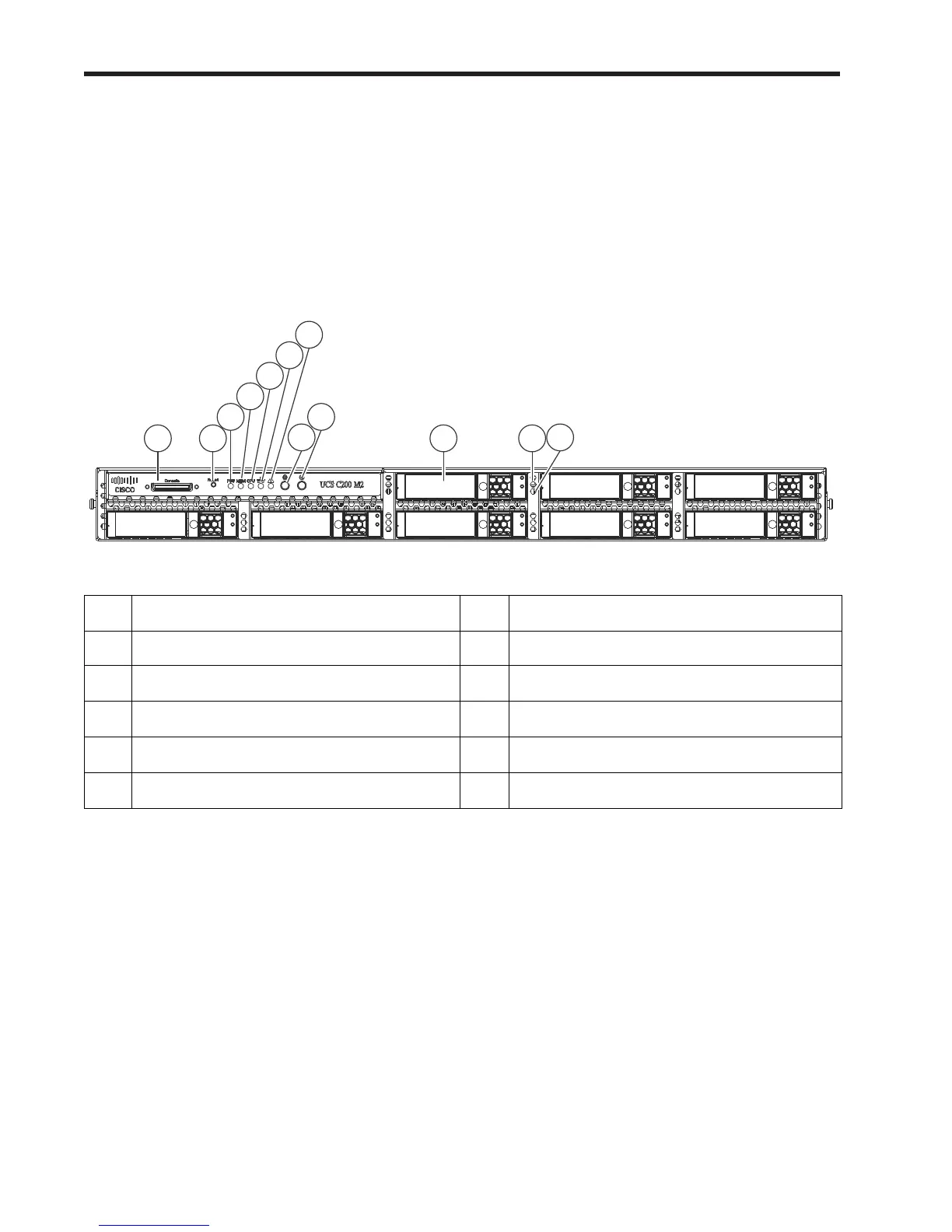
Chassis Front View
Figure 2 shows the Cisco UCS C200 M2 High-Density SFF Rack Server front panel with the standard front
panel control module installed. Figure 3 shows the server with the optional DVD-RW optical drive module
you can configure in place of the front panel control module.
Figure 2 Chassis Front View (Control Panel Installed)
For more information about the KVM cable connection, see KVM CABLE, page 54.
1
KVM console connector
1
1. The KVM connector is not available if the optional DVD-RW optical drive is installed instead of the front panel
control module.
7 System fault LED
2 Reset button 8 Locator button/LED
3
Power supply fault LED
2
2. Not available if an optional DVD-RW drive is installed.
9 Power button/Power status LED
4
Memory fault LED
2
10 Hard drives (up to 8)
5
CPU fault LED
2
11 Hard drive fault LED
6
Network activity LED
2
12 Hard drive activity LED