2-7
Cisco UCS C210 Server Installation and Service Guide
OL-20887-02
Chapter
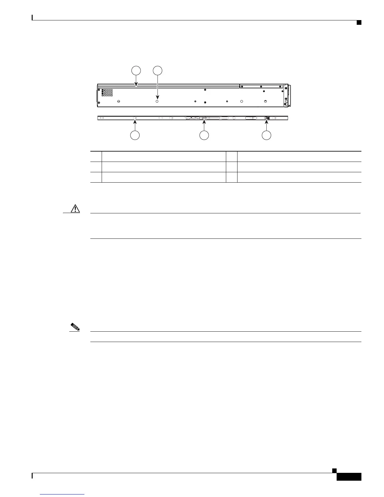
Figure 2-4 Attaching Mounting Brackets to the Server
Step 3 Insert the server into the slide rails:
Caution This server weighs approximately 50 pounds (23 kilograms) when fully loaded with components. We
recommend that you use a minimum of two people when lifting the server. Attempting this procedure
alone could result in personal injury or equipment damage.
a. Align the mounting brackets that are attached to the server sides with the front of the empty slide
rails.
b. Push the server into the slide rails until it stops at the internal stops.
c. Push the plastic installation release clip on each mounting bracket toward the server rear (see item
5 in
Figure 2-4), and then continue pushing the server into the rack until its front flanges touch the
rack posts.
d. Close the front-flange latches to secure the server to the front rack posts.
Step 4 Attach the (optional) cable management arm (CMA) to the rear of the slide rails:
Note The orientation in these instructions refers to a view from the front of the server.
a. Slide the plastic clip on the right end of the CMA length-adjustment slider (item 2) into the rear of
the right slide rail (item 1) until it clips onto the plastic retaining flange inside the slide rail. See
Figure 2-5.
b. Expand the CMA length-adjustment slider (item 2) until its left end aligns with the rear of the left
slide-rail assembly (item 3).
c. Slide the innermost CMA attachment clip (item 4) into the rear of the left slide rail (item 3) and clip
it onto the CMA flange that is on the mounting bracket that is attached to the server.
d. Attach the two-hole slotted bracket (item 5) that is on the left end of the CMA length-adjustment
slider to the left slide rail. Fit the two-hole slotted bracket over the two pegs inside the slide rail.
e. Attach the outermost CMA attachment clip (item 6) onto the CMA flange that is on the left slide rail.
1 Rear of server 2 Mounting peg (four)
3 Mounting bracket 4 Removal release clip
5 Installation release clip