Step 1 Connect the two connectors on one end of the cable to the PCIE-A1 and PCIE-A2 connectors on the drive backplane.
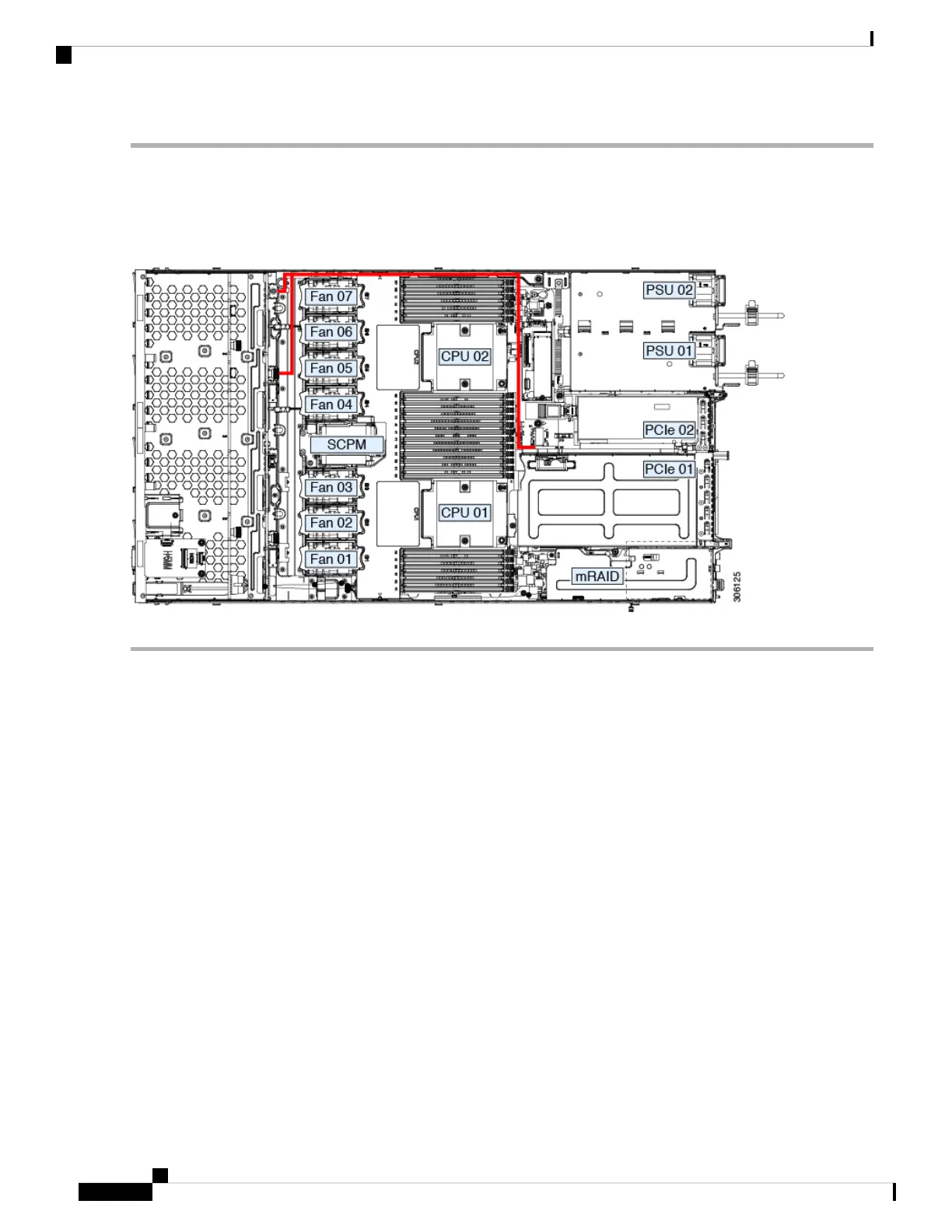
Step 2 Route the cables through the chassis cable guides to the rear of the server as shown below.
Step 3 Connect the single connector on the other end of the cable to the PCIE-FRONT connector on PCIe riser 2.
Figure 10: PCIe Cabling to Drive Backplane
Replacing HHHL Form-Factor NVMe Solid State Drives
This section is for replacing half-height, half-length (HHHL) form-factor NVMe SSDs in the PCIe slots. To
replace 2.5- or 3.5-inch NVMe SSDs in the front-panel drive bays, see Replacing a Front-Loading NVMe
SSD, on page 16.
HHHL SSD Population Guidelines
Observe the following population guidelines when installing HHHL form-factor NVMe SSDs:
• Two-CPU systems—You can populate up to 2 HHHL form-factor SSDs, using PCIe slots 1 – 2.
• One-CPU systems—In a single-CPU system, PCIe riser 2/slot 2 is not available. Therefore, the maximum
number of HHHL form-factor SSDs you can populate is 1, in PCIe slot 1.
HHHL Form-Factor NVME SSD Requirements and Restrictions
Observe these requirements:
• All versions of the server support HHHL form-factor NVMe SSDs.
Observe these restrictions:
Maintaining the Server
20
Maintaining the Server
Replacing HHHL Form-Factor NVMe Solid State Drives

 Loading...


