As instructed in the first step of this wiring procedure, turn off the DC power source from your facility’s
circuit breaker to avoid electric shock hazard.
Caution
Step 1 Turn off the DC power source from your facility’s circuit breaker to avoid electric shock hazard.
The required DC input cable is Cisco part CAB-48DC-40A-8AWG. This 3-meter cable has a 3-pin connector
on one end that is keyed to the DC input socket on the power supply. The other end of the cable has no connector
so that you can wire it to your facility’s DC power.
Note
Step 2 Wire the non-terminated end of the cable to your facility’s DC power input source.
Step 3 Connect the terminated end of the cable to the socket on the power supply. The connector is keyed so that the wires align
for correct polarity and ground.
Step 4 Return DC power from your facility’s circuit breaker.
Step 5 Press the Power button to boot the server to main power mode.
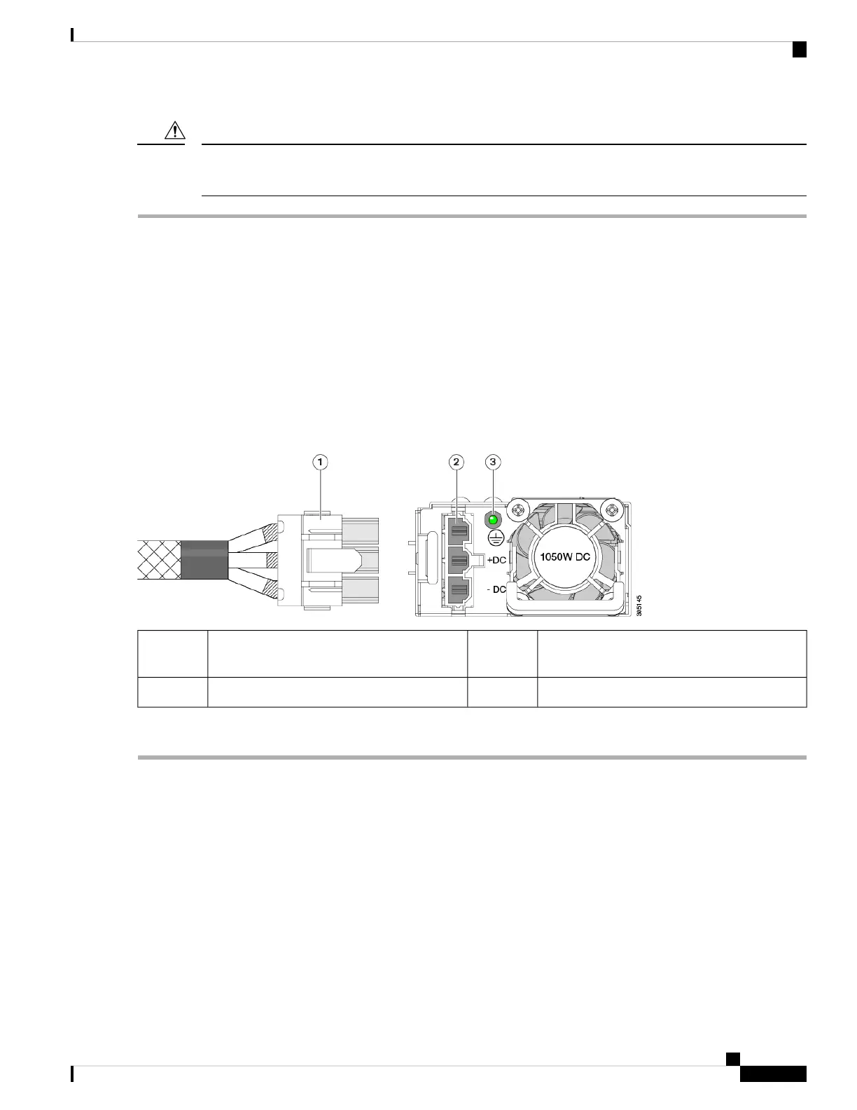
Figure 30: Installing DC Power Supplies
PSU status LED3Keyed cable connector
(CAB-48DC-40A-8AWG)
1
-Keyed DC input socket2
Step 6 See Installation Grounding, page 3-66 for information about additional chassis grounding.
Grounding for DC Power Supplies
AC power supplies have internal grounding and so no additional grounding is required when the supported
AC power cords are used.
When using a DC power supply, additional grounding of the server chassis to the earth ground of the rack is
available. Two screw holes for use with your dual-hole grounding lug and grounding wire are supplied on the
chassis rear panel.
Maintaining the Server
55
Maintaining the Server
Grounding for DC Power Supplies

 Loading...


