Mounting Screws
Two types of mounting screws are provided in separate packages to attach the mounting brackets to the chassis.
Take care to use the correct screw type and washers for the required mounting option (rack mounting or wall
mounting). The following table shows the differences between rack-mounting and wall-mounting screws.
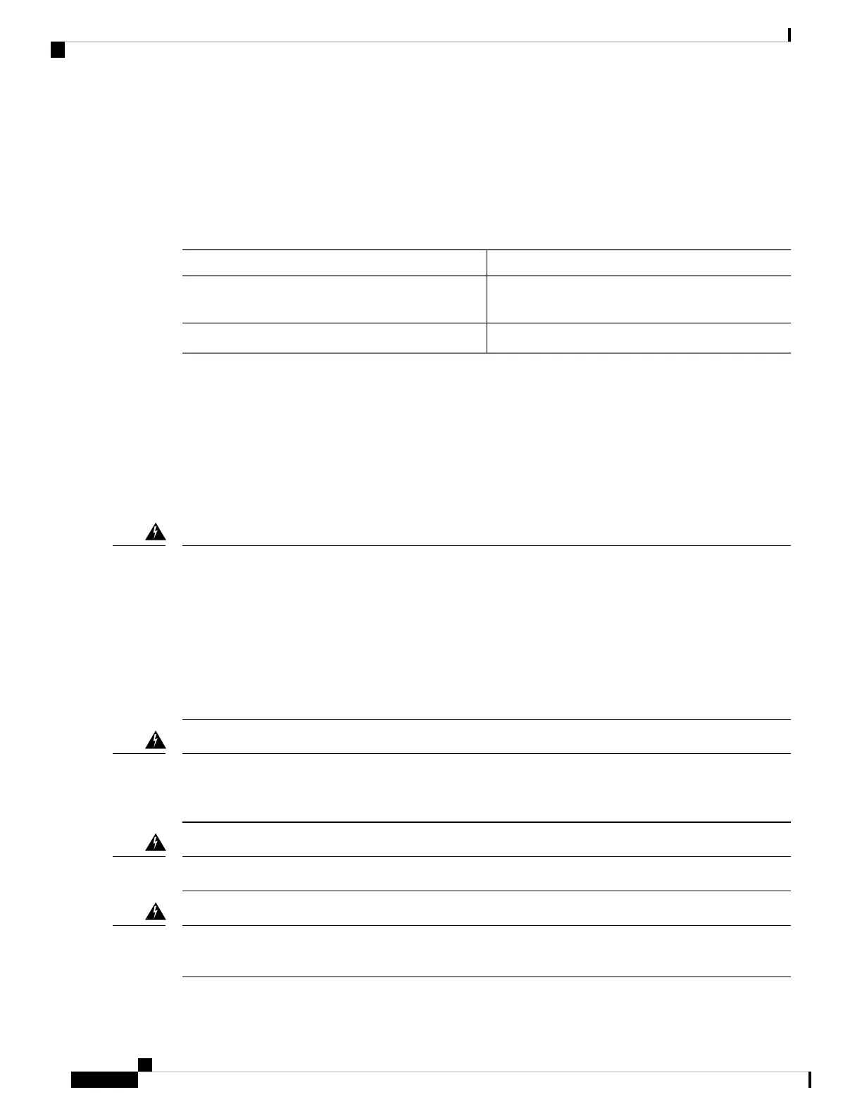
Table 1: Difference Between Rack-Mounting and Wall-Mounting Screws
Wall-Mounting ScrewsRack-Mounting Screws
Four 6–32 slotted hexagonal head screws (two per
bracket) and four plastic washers
Eight countersunk Phillips head screws (four per
bracket)
Washers are requiredWashers are not required
Mounting the Chassis on a Rack
To mount the chassis on a rack:
Before you begin
Your chassis ships with a pair of brackets and mounting screws for use with a 19-inch rack. For information
about the mounting screws that you must use, see Mounting Screws, on page 6.
To prevent bodily injury when mounting or servicing this unit in a rack, you must take special precautions to
ensure that the system remains stable. The following guidelines are provided to ensure your safety:
• If the rack is provided with stabilizing devices, install the stabilizers before mounting or servicing the
unit in the rack. Statement 1006
• The unit should be mounted at the bottom of the rack if it is the only unit in the rack.
• When mounting the unit in a partially filled rack, load the rack from the bottom to the top with the heaviest
component at the bottom of the rack.
Warning
This equipment must be grounded. Never defeat the ground conductor or operate the equipment in the absence
of a suitably installed ground conductor. Contact the appropriate electrical inspection authority or an electrician
if you are uncertain that suitable grounding is available. Statement 1024
Warning
Take care when connecting units to the supply circuit so that wiring is not overloaded. Statement 1018
Warning
To prevent the system from overheating, do not operate it in an area that exceeds the maximum recommended
ambient temperature of: 40 °C (104 °F). Statement 1047
Warning
Installing the Cisco VG310 and Cisco VG320 Voice Gateways
6
Installing the Cisco VG310 and Cisco VG320 Voice Gateways
Mounting Screws