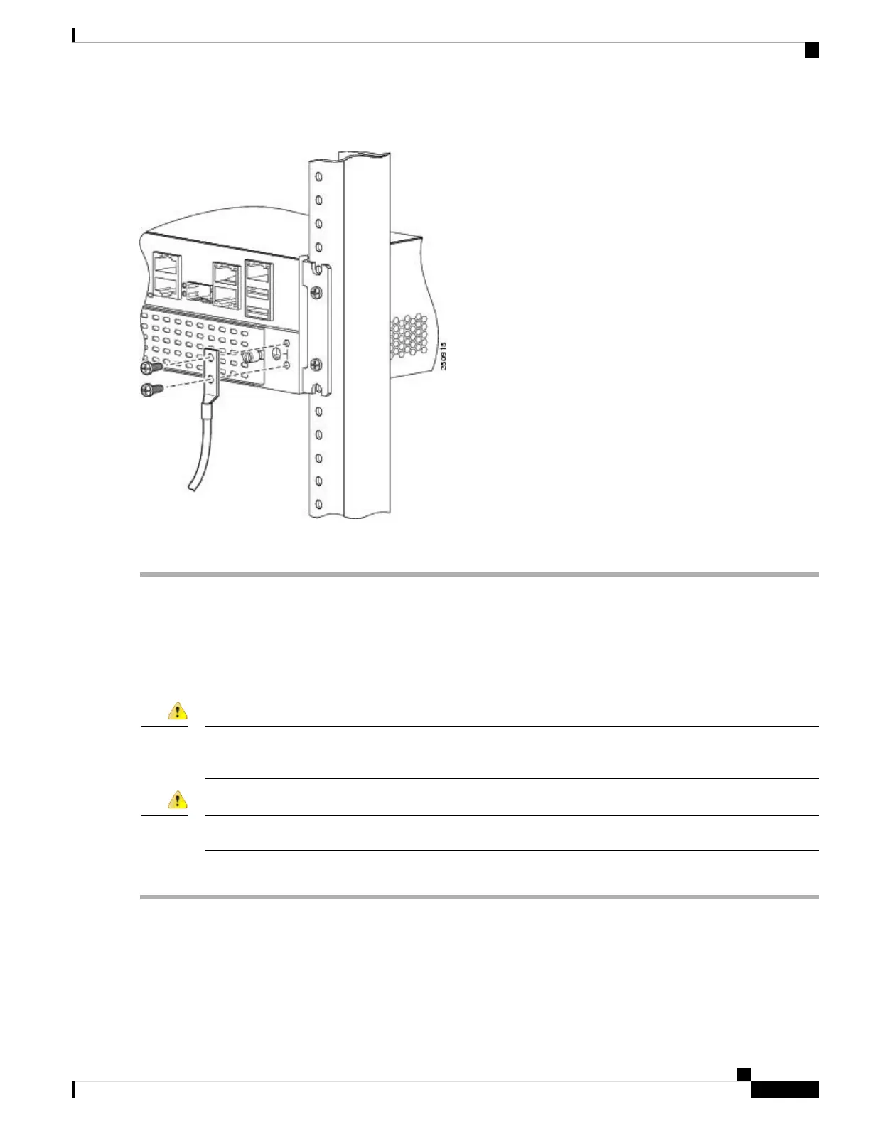
Figure 4: Chassis Ground Connection on the Router
Step 4 Connect the other end of the ground wire to a known reliable earth ground point at your site.
Power-On Procedure
Perform this procedure to power on your Cisco VG450 Voice Gateway, and verify that it goes through its
initialization and self-test. When this is finished, the Cisco VG450 Voice Gateway is ready to configure.
This unit might have more than one power supply connection. All connections must be removed to de-energize
the unit. Statement 1028
Danger
Installation of the equipment must comply with local and national electrical codes. Statement 1074
Danger
To power on the Cisco VG450 Voice Gateway, perform the following:
Step 1 Power on your terminal or PC, and configure it for 9600 bps, 8 data bits, 1 stop bit, and no parity.
Step 2 Move the Cisco VG450 Voice Gateway power switch to the ON position.
The green LED next to the auxiliary port come on and the fan starts to operate. If this does not happen, see the
Troublehooting section in this guide.
Installing the Cisco VG450 Voice Gateway
11
Installing the Cisco VG450 Voice Gateway
Power-On Procedure