3-20
Cisco 2900 and 3900 Series Hardware Installation
OL-18712-01
Chapter 3 Installing and Connecting the Router
Connecting Power
Wiring Procedure for DC Input on Cisco 2911, 2921, and 2951 Routers
To connect a router to a DC power source, perform the following steps:
Step 1
Remove power from the DC circuit. To ensure that power is removed from the DC circuit, locate the
circuit breaker for the DC circuit, switch the circuit breaker to the OFF position, and tape the
circuit-breaker switch in the OFF position.
Warning
Before performing any of the following procedures, ensure that power is removed from the DC circuit.
Statement 1003
Warning
Use copper conductors only.
Statement 1025
Warning
Only trained and qualified personnel should be allowed to install, replace, or service this equipment.
Statement 1030
Tip
Tip Secure all power cabling when installing this unit to avoid disturbing field-wiring connections.
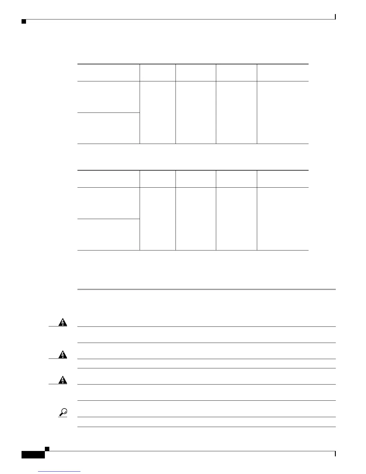
Ta b l e 3-1 DC Wiring Requirements for Cisco 2911 Routers
DC Power Input
DC Input
Wire Size
Safety Ground
Wire Size
Wire Terminal
(Lug)
Overcurrent
Protection
24-36 VDC, 11 A,
positive or negative,
single source or dual
sources
AWG 14
(2.0 mm
2
)
AWG 14 (2.0
mm
2
),
minimum
Amp/Tyco
No. 32957
20 A maximum
36-60 VDC, 4 A,
positive or negative,
single source or dual
sources
Ta b l e 3-2 DC Wiring Requirements for Cisco 2921 and 2951 Routers
DC Power Input
DC Input
Wire Size
Safety Ground
Wire Size
Wire Terminal
(Lug)
Overcurrent
Protection
24-36 VDC, 17 A,
positive or negative,
single source or dual
sources
AWG 14
(2.0 mm
2
)
AWG 14 (2.0
mm
2
),
minimum
Amp/Tyco
No. 32957
20 A maximum
36-60 VDC, 7 A,
positive or negative,
single source or dual
sources

 Loading...


