5-36
Cisco 2900 Series and 3900 Series Hardware Installation Guide
OL-18712-03
Chapter 5 Installing and Upgrading Internal Modules and FRUs
Replacing Power Supplies and Redundant Power Supplies
Step 5
Install the power switch blank cap by slowly pushing it into the power supply opening on the bezel side
of the chassis. Make sure that the “THIS SIDE UP” label is on top when installing the blank cap. You
will feel it snap into place when it is fully seated. See
Figure 5-28
Step 6
Replace the bezel assembly by lining up the holes in chassis with the connectors on the bezel. Slowly
push the bezel assembly into place until it is fully seated.
Step 7
Install the power supply blank panel into the power supply opening on the I/O side of the chassis by
pushing it into place, as shown in
Figure 5-27. Make sure that the flange with the marking “THIS SIDE
UP” is facing up.
Step 8
Tighten the two captive screws with a number 1 Phillips head screw driver after the power supply blank
panel is fully seated.
Replacing the Cisco 2911 Router Redundant Power Supply
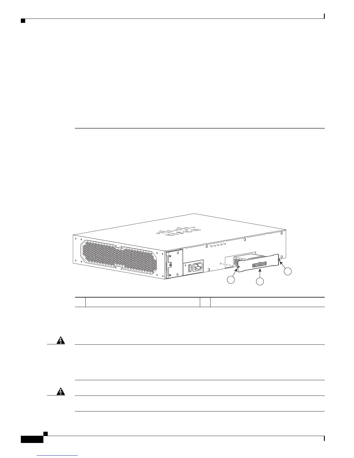
The redundant power supply (RPS) for the Cisco 2911 router is an external RPS. The external RPS
attaches to a connector on the front of the router. For an RPS to be attached, the Cisco 2911 must be
fitted with an RPS adapter. See
Figure 5-29. See the “Installing and Removing a Redundant Power
Supply Adapter” section on page 5-42.
Figure 5-29 Cisco 2911 Redundant Power Supply Adapter
.
Replacing the Cisco 2921, Cisco 2951, or Cisco 3900 Series Power Supply
Warning
Blank faceplates and cover panels serve three important functions: they prevent exposure to
hazardous voltages and currents inside the chassis; they contain electromagnetic interference (EMI)
that might disrupt other equipment; and they direct the flow of cooling air through the chassis. Do not
operate the system unless all cards, faceplates, front covers, and rear covers are in place.
Statement
1029
Warning
This unit might have more than one power supply connection. All connections must be removed to
de-energize the unit.
Statement 1028
1 RPS Adapter 2 RPS fastening screws (2)
250980
1
2
2

 Loading...


