5-42
Cisco 2900 Series and 3900 Series Hardware Installation Guide
OL-18712-03
Chapter 5 Installing and Upgrading Internal Modules and FRUs
Replacing Power Supplies and Redundant Power Supplies
Installing and Removing a Redundant Power Supply Adapter
The redundant power supply (RPS) for the Cisco 2911, 2921, or 2951 router is an external
Cisco
RPS 2300. To connect the RPS, the router must be fitted with an RPS adapter. A blank panel must
be removed before installing the RPS adapter. The external RPS attaches to a connector on the front of
the adapter. See
Figure 5-32.
Note
After connecting to the RPS2300, Cisco 2900 series routers require a reboot.
Tip
For information specific to the RPS 2300, see the Cisco Redundant Power Supply System Hardware
Installation Guide at:
http://www.cisco.com/en/US/docs/switches/power_supplies/rps2300/hardware/installation/guide/2300
hig.html
Depending upon RPS configuration, more than one router can be backed up.
Caution
Failure to follow the RPS Installation or Removal procedures can cause damage to the router, RPS
adapter, RPS cable, or RPS.
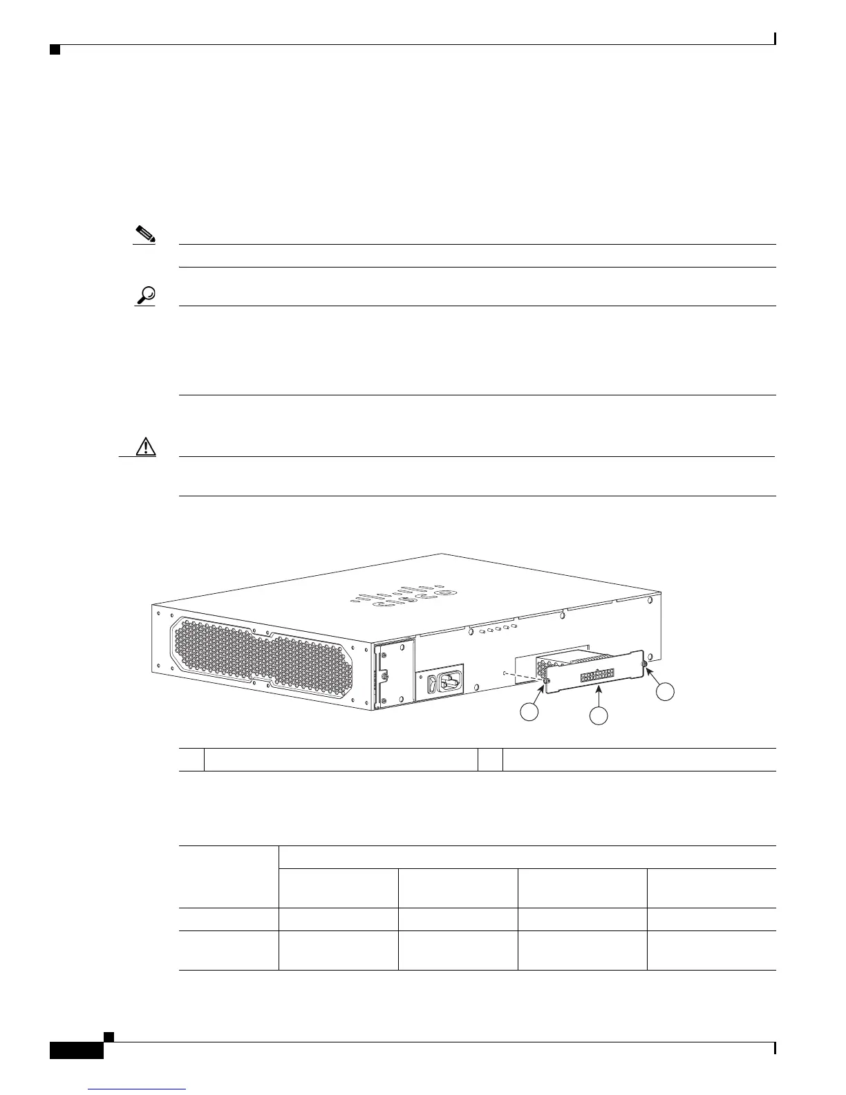
Figure 5-32 Cisco 2911 Redundant Power Supply Adapter
.
Table 5-3 shows RPS 2300 backup capabilities when coupled with Cisco 2900 series ISRs.
1 RPS Adapter 2 RPS fastening screws (2)
250980
1
2
2
Ta b l e 5-3 RPS 2300 Backup Capabilities
Power Mode
Quantity and Type of RPS 2300 FRU
Quantity 1
C3K-PWR-750WAC
Quantity 2
C3K-PWR-750WAC
Quantity 1
C3K-PWR-1150WAC
Quantity 2
C3K-PWR-1150WAC
2911 in RPS 1 2 1 2
2921, 2951 in
RPS
0 1 0 1

 Loading...


