5-32
Cisco 2900 Series and 3900 Series Hardware Installation Guide
OL-18712-03
Chapter 5 Installing and Upgrading Internal Modules and FRUs
Replacing Power Supplies and Redundant Power Supplies
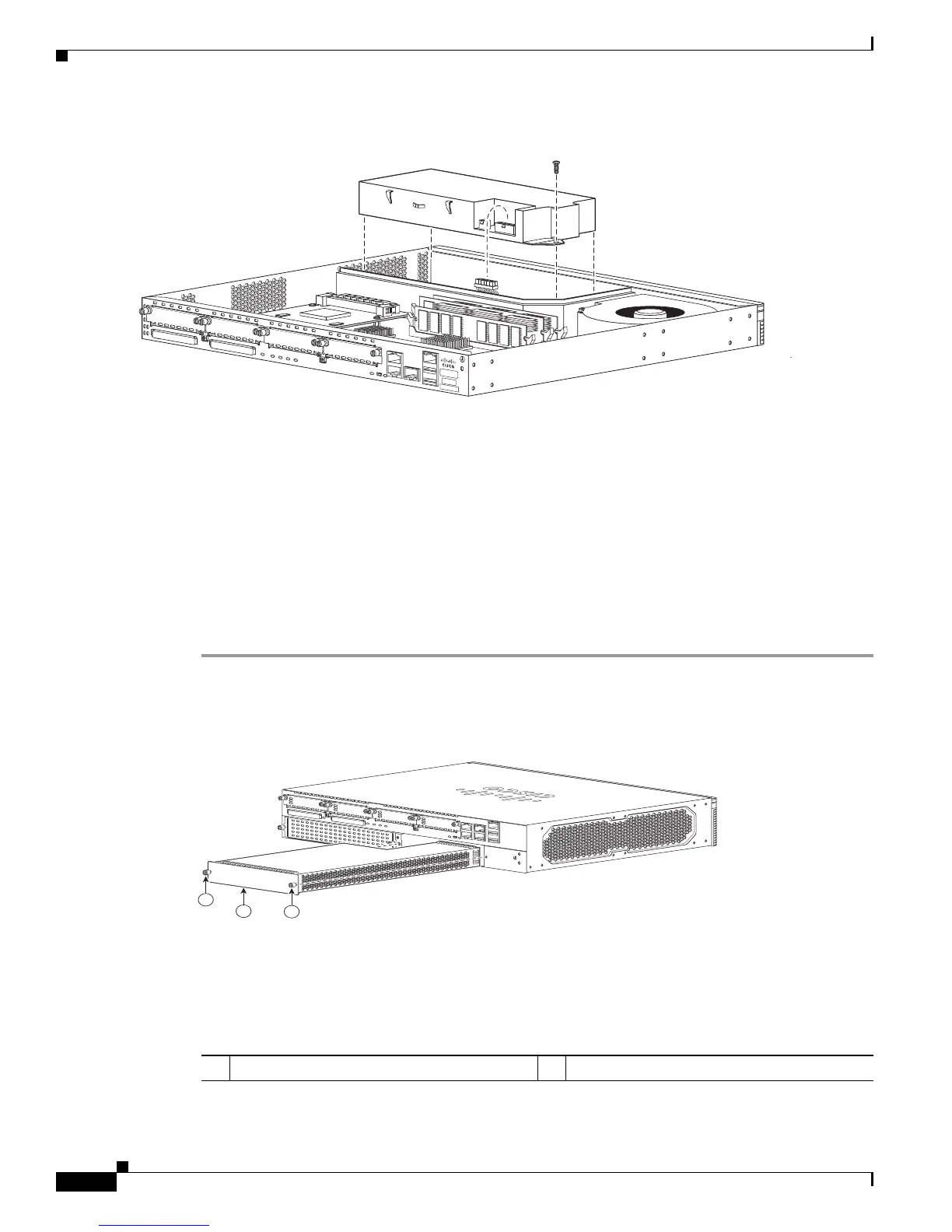
Figure 5-25 Lifting the 2901 Power Supply In or Out
Step 7
Insert the replacement power supply into the chassis. See Figure 5-25. Insert the screws that fasten the
power supply to the chassis. See Figure 5-24.
Step 8
Connect the power supply cable to the power supply connector. Replace the chassis cover and connect
power to the router.
Replacing the Cisco 2911 Router Power Supply
Several power supply options are available for the Cisco 2911 router. See Table 5-2. All of the power
supply options have the same modular form factor for easy removal and replacement.
Perform the following steps to replace the 2911 power supply:
Step 1
Read the “Safety Warnings” section on page 5-2 section and disconnect the power supply before you
perform any module replacement.
Figure 5-26 Cisco 2911 Power Supply Components
.
250970
DO NOT REMOVE DURING NETWORK OPERATION
DO NOT REMOVE DURING NETWORK OPERATION
1 Power supply 2 Power supply fastening screws (2)
DO NOT REMOVE DURING
NETWORK OPERATION
DO NOT REMOVE DURING
NETWORK OPERATION
250977
1
2
2

 Loading...


