1 Introduction
8
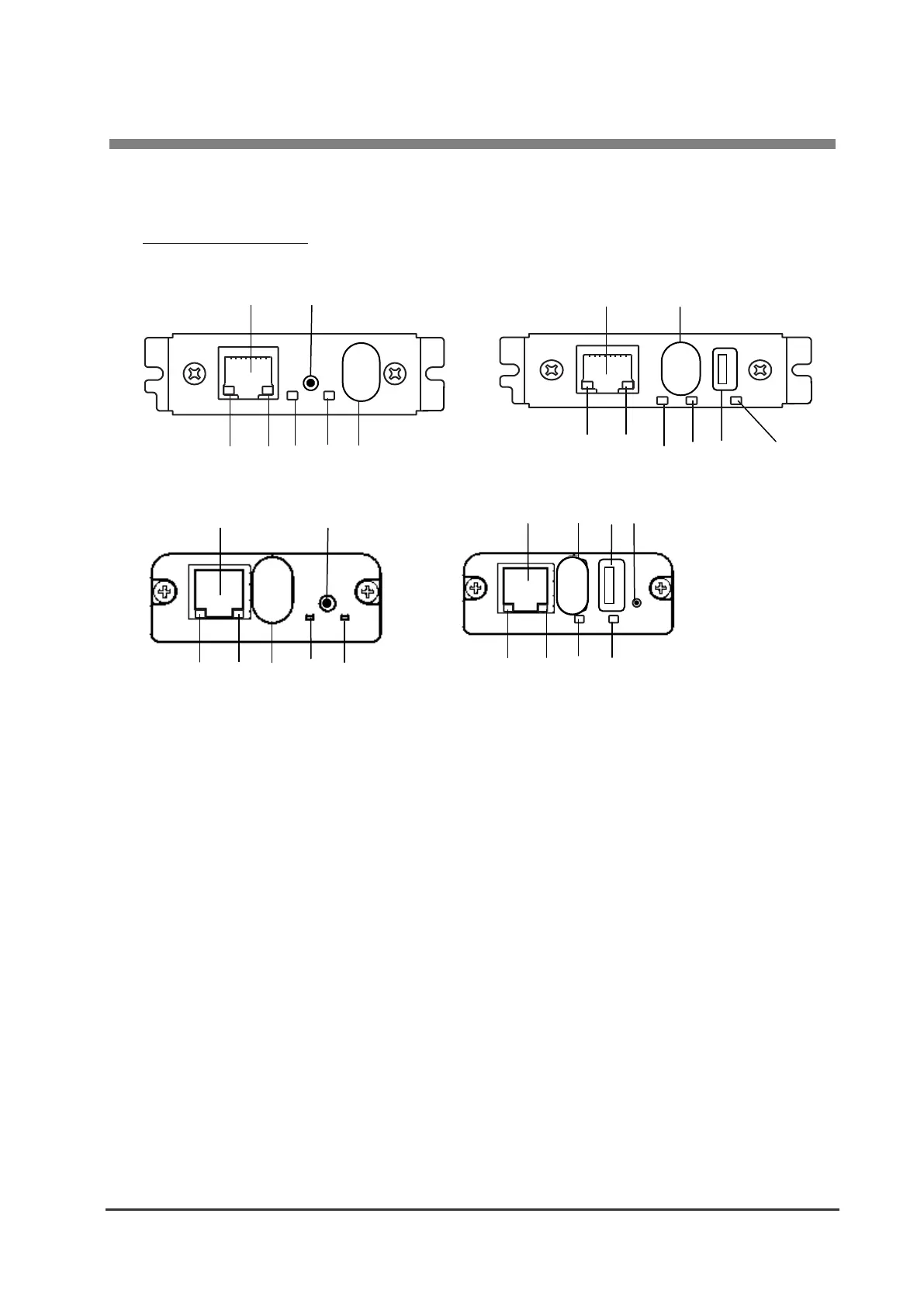
1-4. Part Names and Functions
Interface Board Unit
IF1-WFx4 (USB 1 port) IF1-WFx5 (USB 2 ports)
IF2-WFx5 (USB 1 port) IF2-WFx6 (USB 2 ports)
① RJ45 connector (compatible with 10Base-T/100Base-TX)
Connection for LAN cable
② Ethernet transmission speed LED indicator (green)*
1
Shows Ethernet transmission speed with steady/blinking light.
③ Ethernet status indicator LED (yellow)*
1
Shows Ethernet connection status (disconnected, receiving data, etc.).
④ Ethernet/WLAN status LED indicator (green)*
1
⑤ Ethernet/WLAN status LED indicator (red)*
1
Shows transmission, connection and error statuses with steady/blinking lights combinations.
⑥ Panel button*
2
Used to operate the Interface board.
⑦ USB Wi-Fi adaptor / USB connector (First)
Connection for the Wi-Fi adapter.
⑧ USB connector (Second)
This exists only on IF1-WFX5/IF2-WFx6.
*1 See 3-5, Display status by LED (page 20) for indicator details.
*2 See, 3-2, Using the Panel Button (page 16) for panel button operations.
 Loading...