<SM-13024-A>
21
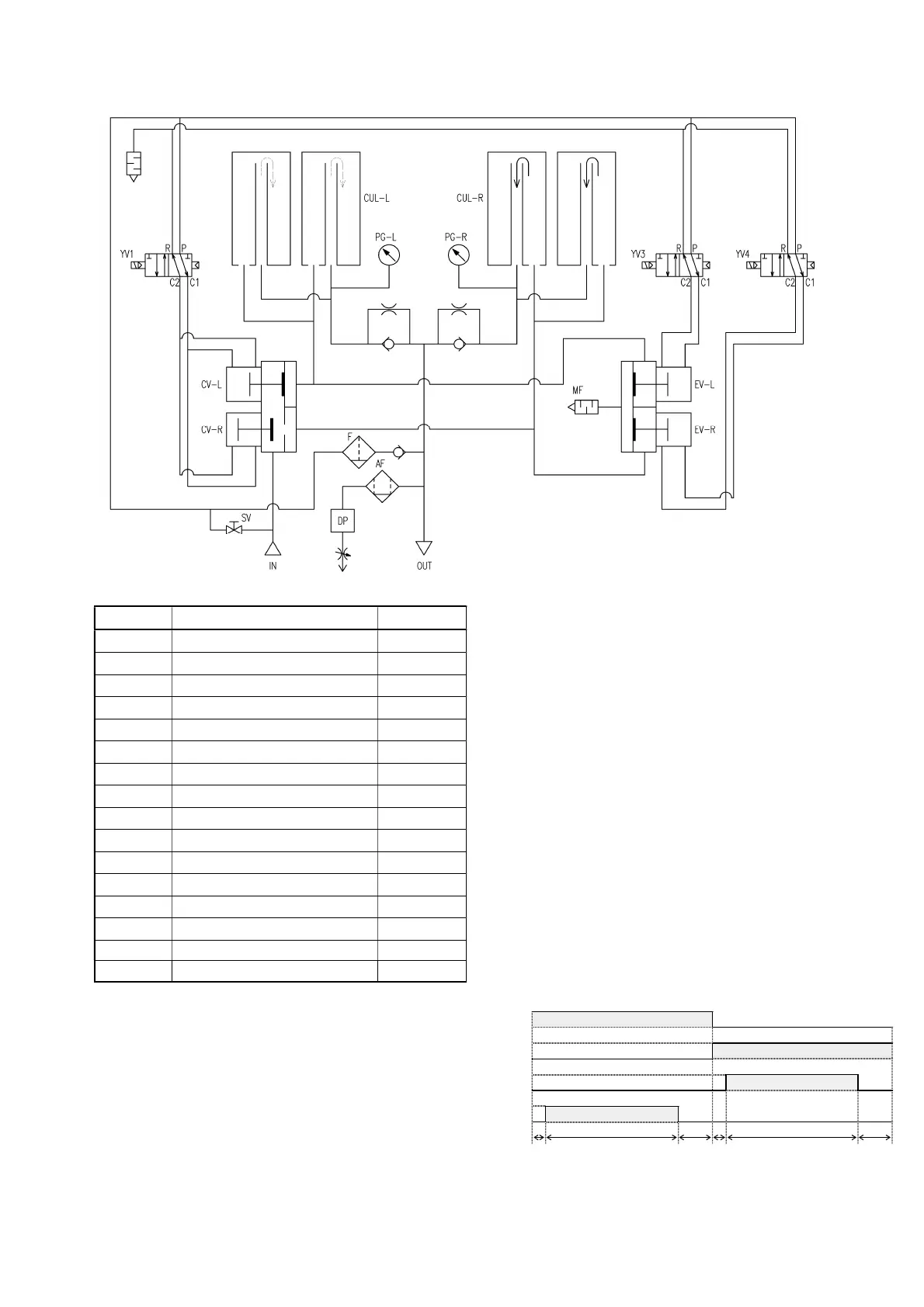
8-4Systemdiagram
Model Partsname Numbers
CV-R Airactivationvalve(Right) 1
CV-L Airactivationvalve(Left) 1
EV-R Exhaustvalve(Right) 1
EV-L Exhaustvalve(Left) 1
YV1 Solenoidvalve 1
YV3 Solenoidvalve 1
YV4 Solenoidvalve 1
CUL-R Desiccantvessel(Right) 1
CUL-L Desiccantvessel(Left) 1
MF Silencer 1
AF Microalescer 1
DP Dew-pointsensor 1
PG-R Pressuregauge(Right) 1
PG-L Pressuregauge(Left) 1
SV Manualvalve 1
F Filter 1
Timechartdrawing
Normalprocessisshowninthefollowing.
Thestate(C,F)afterdesorptioniscompletedis
heldatthetimeofenergysavingIfsubsequentdew
pointbecomes bad, change willberesumed andit
willreturntonormalprocess.
B、Eisdesorption(regeneration)time
C,Fshowspressurerisingtime.
ThedampcompressedairwhichenteredfromIN
goesintodesiccantvesselCUL-LthroughValve
CV-R.Thedampcompressedairflowstheinside
of the desiccant equally, with the desiccant, it
adsorbsthesteamincompressed air, turns into
super-dryair,and comes outofOUT through a
check valve. A part of super-dry air
decompressed through the orifice goes into
desiccant vessel CUL-R, and it is used for
reproductiondrynessofthedesiccantofCUL-R,
and is emitted to the atmosphere. A part of air
whichcameoutofOUTisled to thedewpoint
sensorDP,anddewpointmeasurementiscarried
out. It goes into the energy-saving mode which
switchesbythedewpointandextendstime.
(D
esorptionprocessisended,andafterthat,both
vessels are held in pressure rising state and
carryoutchangetimeextension.
)
吸着R
吸着L
脱着R
脱着L
1秒 100秒 19秒 1秒 100秒 19秒
(B) (C)
(E) (F)
AbsorptionR
AbsorptionL
DesorptionL
DesorptionR
1sec
(A)
100sec
(B)
19sec
(C)
1sec
(D)
100sec
(E)
19sec
(E)
Orifice
Checkvalve