Clarion
Printed
in
China
/
impnme
au
Chine
/
ImpresQ
en
China
/
1±<POOfPlJIJ
1999/11
(W.C)
284-9114-00
InstaliationlWire Connection Guide
Gufa de installaci6n/conexi6n de cables
BID
...
-1
. BEFORE STARTING I
RATIFS I ANTES DE COMENZAR
11f~tif1=zm
1. This set is exclusively for use in cars with a
negative ground
12
V power supply.
2. Read these instructions carefully.
3. Be sure to disconnect the battery " 8 " terminal
before starting. This is to prevent short circuits
during installation. (Figure
1)
Cet est concu exclusivement les
voitures !'alimentation est de
12 V masse
negative.
Veuillez lire attentivement ces instructions.
3.
Veillez debrancher la borne
batterie avant d'installer
I'''l"ln;;rpil
court
..
circuil. (Figure 1)
1.
Esta unidad ha sido disenada para utilizarse
exclusivamente en autom6viles con fuente de
alimentaci6n de
12
V,
Y negativo
amasa.
2. Lea cuidadosamente estas instrucciones.
3. Antes de comenzar la instalaci6n, cerci6rese de
desconectar el
terminal"
8 " de la baterfa. Esto es
para evitar cortocircuitos durante la instalaci6n.
(Figura
1)
1.4:~
fMJi.
ffl
y
Fli
jJ.~Ut!
lli
-;Jg
12 V,ffl.
f&
~
1t1!.
i¥J
$
!*J
0
2.
j;i'i1H!Ilr~~*iM~Jj~o
3.
*~I1t*ftJltr,
j;i'iTiffliJ..BI~*'I'Flijtl!,i¥J
"(-',)"
tit
i!~
-;Jg
n,;7ll:1'E't(~4'
~:tHIT~o
(rn
1 )
Car battery
BaUerle de voilure
Bateria del autom6vil
i't$f;f~i1!l
Figure
1 /
Figure
1 /
Figura
1 /
IE
1
/
PRECAUCIONES
PARA
LA
INSTALACION
/
~~a<Jj!.~I9i
BID
...
-2.
CAUTIONS
ON
INSTALLATION
/ :1"\1"'11""'"
1. Prepare all articles necessary for installing the
source unit before starting.
2. Install the unit within 30° of the horizontal plane.
(Figure
2)
3. If you have to do any work on the car body, such as
drilling holes, consult your car dealer beforehand.
4. Use the enclosed screws for installation. Using
other screws can cause damage. (Figure 3)
Avant
cle
commencer I'installation
cle
I'apparei!
pilote, preparez toutes les pieces necessaires.
2 Installez aI'horizontale, aun angle maxi·
mum de
2)
3. Si vous devez effectuer des travaux sur
la
carrosserie,
par
exemple percer des trollS,
consu!tez vOlre concessionnalre auto aupalavanL
4 Utilisez les vis fournies pour !'installation.
Lutilisalion de toute autre vis peut causer des
dommages. (Figure
3)
1.
Antes de comenzar la instalaci6n, prepare todos
los elementos necesarios para instalar la unidad
fuente.
2.
Instale la unidad con un angulo de 30° sobre el
plano horizontal. (Figura 2)
3.
Si tiene que realizar cualquier trabajo en la
carrocerfa, como taladrado
de
orificios, etc.,
consulte al proveedor de su autom6vII.
4.
Utilice los tornillos suministrados para la
instalaci6n. La utilizaci6n de otros tornillos podrfa
resultar en danos. (Figura
3)
].
't('fgJltrw:iitiffi]fll't(~i:tJLEJTfIfi'B~!Io/Jr\1lo
2.
fft
14'
J'it:
t1Ii
':k:'fg
Jjj(;
1::]
;K
If
iii
Jjj(;
30
IJt
X
Jrlo
(/J/
2)
3.
PIi*~tE'ifpt~.t:iZt1TJ',\Jdt,
ttplit~1L':,:~~,
i:i'i(.i)f~
i3<J
1"1:
'if
B~
ff1j
1!f
jfjf
i?f
i.~L
4.
1<'
'fg
HJ
i:f'f
f'1!
ffl
"ft
frJt~
{ft
i¥J
~
i'~.
0
f'1!
jllyt'8
i¥J
~
i'f:
PI
~~
0tBHf
4'>:fJL
(
003
)
1-
- - -
I
,
I
,
,
Max.
5/16"(8 mm)
~
- - - Max. 5/16"(8 mm)
Max.
5/16"(8 mm)
MA
5/16" 8 mm)
Figure
3/
Figure
3/
Figura
3/IE
3
Figure
2/
Figure
2/
Figura
2/
IE
2
Chassis / Chassis / Chasis
!til#! Chassis / Chassis / Chasis /
-IJtflJ
INSTALACION
DE
LA
UNlOAD
FUENTE
13::*JHr-J~~
BID
...
-3.
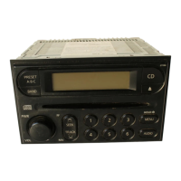
INSTALLING
THE
SOURCE
UNIT
/"u"""
This unit is designed for fixed installation
in
the dash-
board.
1.
When installing the source unit
in
NISSAN vehicles,
use the parts attached to the unit and follow the
instructions
in
Figure
4.
When installing the source unit
in
TOYOTA
vehicles
(Figure 5), use the parts attached to the vehicle and
follow the instructions
in
Figure
5.
2. Wire as shown
in
Section
6.
3.
Reassemble and secure the unit
in
the dashboard
and set the face panel and center panel.
Cet ost conyu pour otro
installc')
dans
!e
tableau
boreJ.
I.
vous instaliez I'apparell pilote dans
un
vehicule
NISSAN. utilisez !es pieces attacl1ees I'oppareli
et suivez les Instnlclions de
la
figule
Si vous inslallez dans un vel1lcule
-fOYOIA (Figure !es pieces allachees
v6hicu!e el suivez instructions de
!a
figure 5
2.
HacconJez comme indiqu6 dans
Ie
parawaphe
6.
'l
Montez et fixez I'appal eil dans
to
talliew I de
hOlT]
posez
Ie
panneau avant et
Ie
pannoau
central
Esta unidad ha sido disenada para instalarse fijada al
tablero de instrumentos.
1.
Cuando instale la unidad fuente en un autom6vil
NISSAN, utilice las piezas suministradas con la
unidad, y siga las instrucciones de la Figura
4.
Cuando instale la unidad fuente en un autom6vil
TOYOTA (Figura 5), utilice las piezas fijadas
al
autom6vil y siga las instrucciones de la Figura
5.
2.
Conecte los cables como
se
muestra
en
la
Secci6n
6.
3.
Ensamble y asegure la unidad al tablero de
instrumentos, y coloque
el
panel frontal y el panel
«entral.
].
l'r:
N1SSAN
(
EJ
F)
ib($.t1<''fgs;J,
fi'if'1!ffl
:i:fJlfi]frtji
If]
111m
cIf
j]!
WHfJ
4
JiJr
7j~
i¥J
JI1
iJ
I0
tETOYOTA
($[BJ
1"1:$
(005) .t':lC'fgsj,
i'i'if'1!Jf
HJtJiJiwS0pHf4'clfjgHtHCf!5
JiJr7]~S<Jj!-iiJl
0
2.
J't(~
6
l'iIliJf7f,*j~t~"
Ji
fJf
<idl~()('&
tfJi
j'll<JHft
cIf
{'1!
Z.
2p
/i'iI.
'!:C:liz
iiitUIi
I}JfJi
"
Mounting
Screw Holes
Orifices
de montage
Side
View
of
the
Source
Unit
Vue !alem!o
Orificios
para
los
tornillos
de montaje
~~!IiJ~HL----,
Vista
lateral
de
la
unidad
fuente
:£tJU'tJlil1t:t\1fI
r r
Screw holes for NISSAN vehicle
Orifices pour un vehioute NISSAN
Orificios para tomillos para
un
autom6vil NISSAN
NlSSAN
\
Ll
)
i\Jf'·[I~!iJiR{'f~TL
Screw holes for TOYOTA vehicle
Orifices pour
un
vehicule TOYOTA
, Orificios para tomillos para un autom6vil TOYOTA
!IFf
TOYOTA
,1'
W)

 Loading...