NX700/NX700E
- 26 -
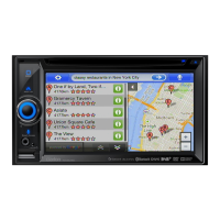
2-8. Installation of Upper case
No. PARTS CODE
Q'T
1. Attach upper case on Main unit, A 310-1831-02 1 * Fit at convex part of
and fix it with machine screw(B). B 714-2604-8B 4 Inner Escutcheon
and hole of upper case.
* Follow screw sequence. (1 to 4)
WORKING DIAGRAM WORKING PROCESS WORKING POINT
B
2
Convex part
hole
(4) (1)
B
(3)
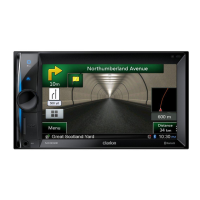
2-7. Installation of Inner Escutcheon
No. PARTS CODE
Q'T
1. Insert FPC(A) in Flex-socket A 039-3448-00 1 * Fit at 2 dowels.
of the front side on Main unit,
and lock by the hands.
2. Fix it with IT screw(B). B 780-2604-50 1
3. Attach it putting the tab of lower side of * Fit at 4 tabs of lower side.
processed Inner Escutcheon
on Main unit.
4. Fix it with screw(C). C 780-2604-52 4
WORKING DIAGRAM WORKING PROCESS WORKING POINT
A
B
㪻㫆㫎㪼㫃
㪤㪸㫀㫅㩷㫌㫅㫀㫋
processed
Inner Escutcheon
C
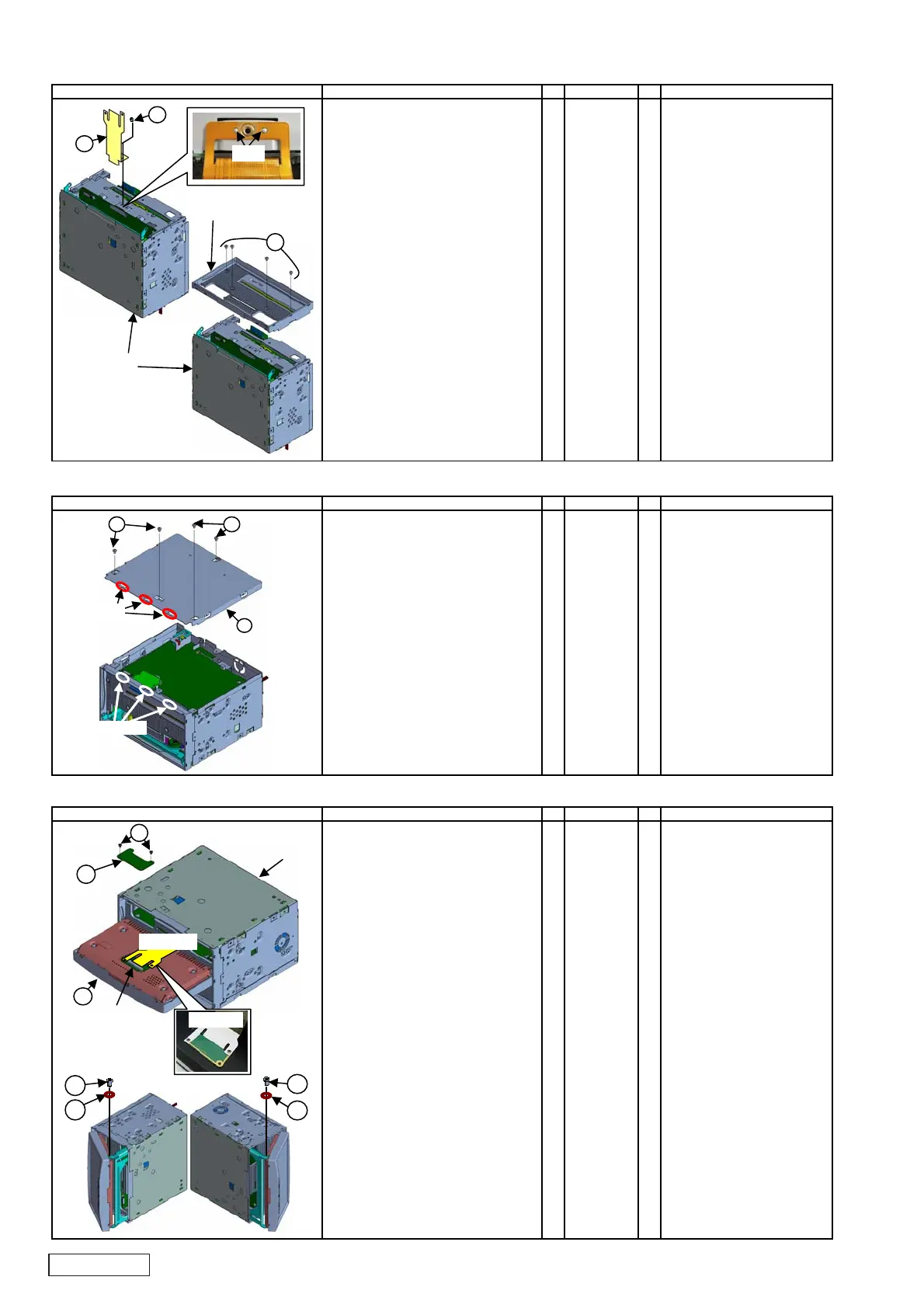
2-9. Installation of Panel ASSY
No. PARTS CODE
Q'T
1. Set the Slide roller of PANEL-ASSY A ----------- 1
in the ditch on the Inner Escutcheon
one by one side, put on Panel.
2. Unlock Flex-socket of
rear side of Panel.
Insert Flex-PWB of Main unit in it,
and lock.
3. Attach Panel cover on Panel, B 039-3502-00 1
and fix it with special screw(C). C 716-1851-00 2
4. Turn it so that the right side of Main unit
ma
become upper sid
while holding PANEL.
5. Align the slide rail with the screw hole
of PANEL, attach the bush(D) D 335-7903-00 1
and fix with special screw(E). E 716-3577-00 1
6. Turn it so that the left side of Main unit
may become upper side.
7. Ali
n the slide rail
with the screw hole of PANEL,
attach the bush(F) F 335-7903-00 1
and fix with special screw(G). G 716-3577-00 1
WORKING DIAGRAM WORKING PROCESS WORKING POINT
A
㪝㫃㪼㫏㪄㫊㫆㪺㫂㪼㫋
㪤㪸㫀㫅㩷㫌㫅㫀㫋
B
C
㪝㫃㪼㫏㪄㪧㪮㪙
D
E
F
G
㪝㫃㪼㫏㪄㪧㪮㪙
 Loading...