NX700/NX700E
- 25 -
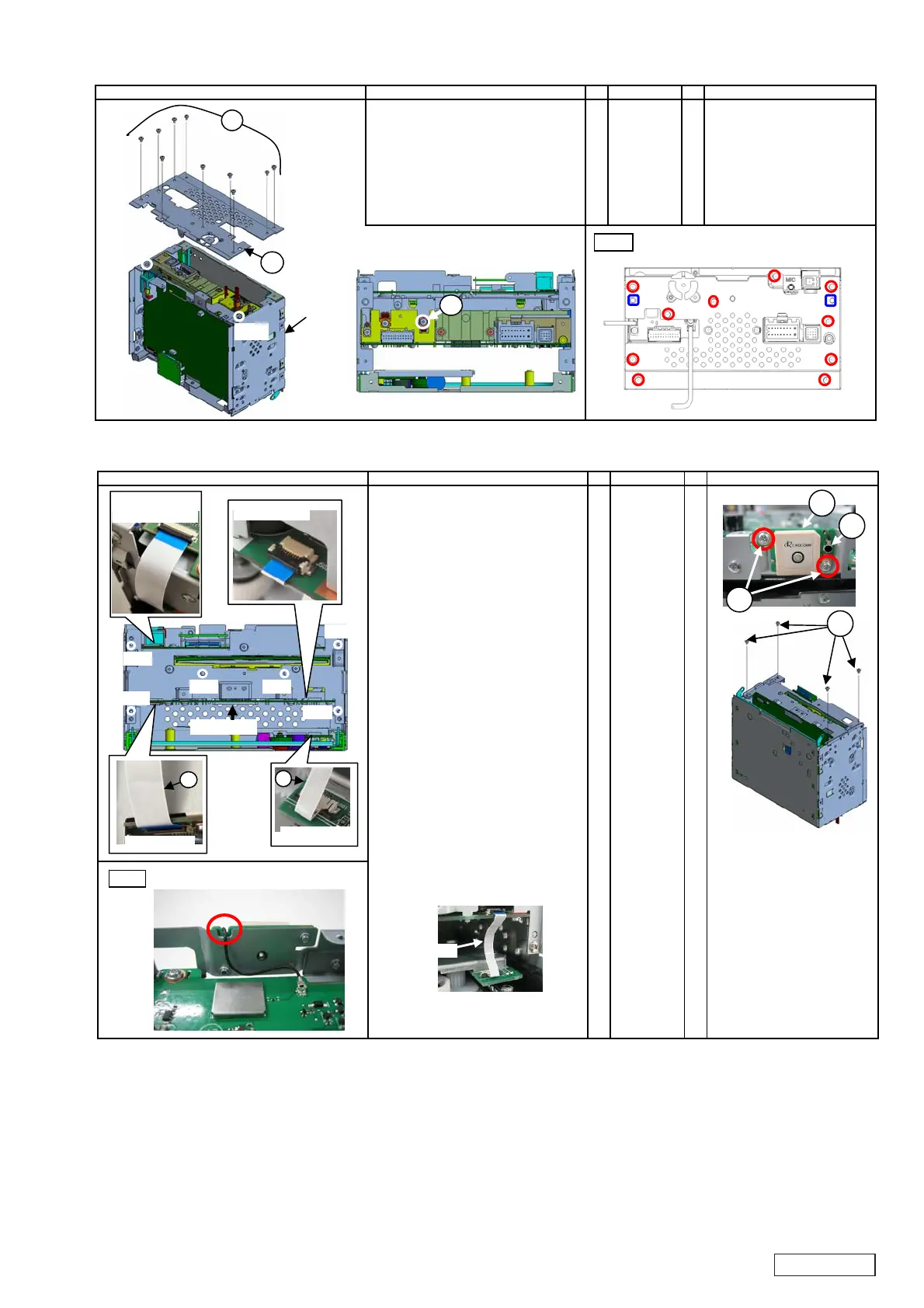
2-5. Installation of Rear cover
No. PARTS CODE
Q'T
1. Fit the metal fittings part
of the USB lead of Main PWB
and the Main PWB holder
with the machine screw(A). A 714-2604-8B 1
2. Attach rear cover on Main unit, B 307-0738-01 1 * Fit at 2 dowels.
and fix it with machine screw(C). C 714-2604-8B 10 * Follow screw sequence. (1 to 10)
WORKING DIAGRAM WORKING PROCESS WORKING POINT
A
B
C
(C)(2)
(Fig.1)
(C)(9)
(C)(1)
(C)(8)
(C)(7)
(C)(6)
(C)(5)
(C)(4)
(C)(3)
(C)(10)
dowel
dowel
dowel
dowel
Main unit
2-6. Installation of Front plate
No. PARTS CODE
Q'T
1. Attach ANT-PWB on the front plate, A ----------- 1
and fix it with machine screw(B)(C). B 780-2604-50 2
C 714-2604-8B 4
2. Insert BT-ANT lead in ANT receptacle D 092-2239-01 1
of ANT-PWB-ASSY.
3. Unlock the following socket.
* J5001 : SLIDE-PWB
* J382 : MAIN-PWB
* J452 : MAIN-PWB
* J502 : MAIN-PWB
* Socket(flip lock) : NAVI-PWB-ASSY
4. Insert FPC(24P) in the socket(J382) E 816-3041-55 1
of MAIN-PWB.
Insert the other side of FPC(24P)
in the socket of NAVI-PWB-ASSY,
and lock by the hands.
5. Insert FPC(8P) in the socket(J5001) F 816-3040-55 1
of Slide PWB, and lock.
6. Insert the other side of FPC
8P
in the socket
J502
of Main PWB,
and lock b
the hands.
7. Process the part of the rest of FFC
8P
as follows.
8. Insert BT-ANT lead in ANT receptacl
of NAVI-PWB-ASSY.
Fi
.1
WORKING DIAGRAM WORKING PROCESS WORKING POINT
(Fig.1)
8P-FFC
C
A
B
D
㪻㫆㫎㪼㫃
Socket (J382)
E
Socket (J452)
Socket (J5001)
Socket (J502)
F
Socket(flip lock)
: NAVI-PWB-ASSY
㪻㫆㫎㪼㫃
㪻㫆㫎㪼㫃
㪻㫆㫎㪼㫃
㪻㫆㫎㪼㫃
㪻㫆㫎㪼㫃
 Loading...