NX700/NX700E
- 24 -
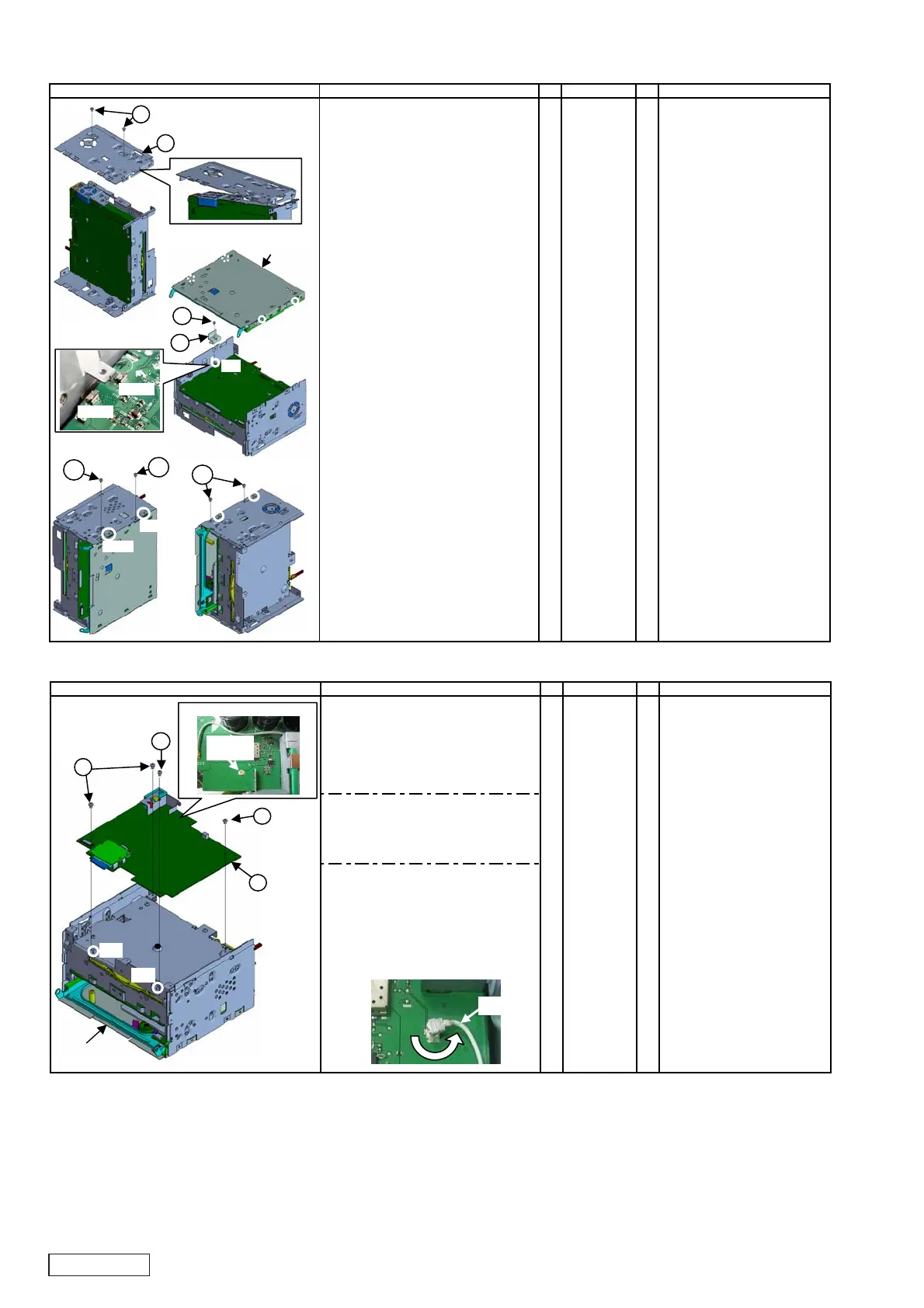
2-4. Installation of Navi PWB
No. PARTS CODE
Q'T
< Only NX700E(QY-5015E-A) >
1. Peel off the masking tape
temporarily stopped
with ANT-lead of Main PWB.
2. Attach NAVI-PWB-ASSY on Main unit. A ----------- 1 * Fit at 2 tabs.
3. Fix it with IT screw(B). B 780-2604-50 4 * Follow screw sequence. (1 to 4)
< Only NX700E(QY-5015E-A) >
4. Insert ANT-lead of Main PWB
in the socket of NAVI-PWB-ASSY.
5. After inserting it, rotate the terminal
of ANT-lead lightly as follows.
WORKING DIAGRAM WORKING PROCESS WORKING POINT
NT-lead
Main uni
Insert
NT-lead
A
B
B
B
㫋㪸㪹
4
< Only NX700E(QY-5015E-A) >
3
2
1
㫋㪸㪹
2-3. Installation of Slide mechanism
No. PARTS CODE
Q'T
1. Attach side chassis L on Main unit, A 312-0503-00 1 * Attach it from the front plate side
and fix it with machine screw(B). B 714-2604-8B 2 diagonally.
* Fit at 2 dowels
on front plate side,
on upper chassis.
2. Attach earth plate on side chassis R C 331-4870-00 1 * Fit at 1 tab.
of Main unit, and fix it
with machine screw(D). D 714-2604-8B 1
3. Attach processed Slide mechanism * Fit at 4 dowels.
on Main unit.
4. Turn the unit to the left,
and check the fittin
at 2 dowel
on Slide mechanism.
Fix it with machine screw(E). E 780-2604-51 2
5. Turn the unit to the right,
and check the fitting at 2 dowels
on Slide mechanism.
Fix it with machine screw(F). F 780-2604-51 2
WORKING DIAGRAM WORKING PROCESS WORKING POINT
E
E
F
TM101
TM102
A
B
C
D
processed
Slide mechanism
w
l
w
l
w
l
w
l
 Loading...