16 VTM1
English
6 . INSTALLATION
VTM1 16 01-12-2010
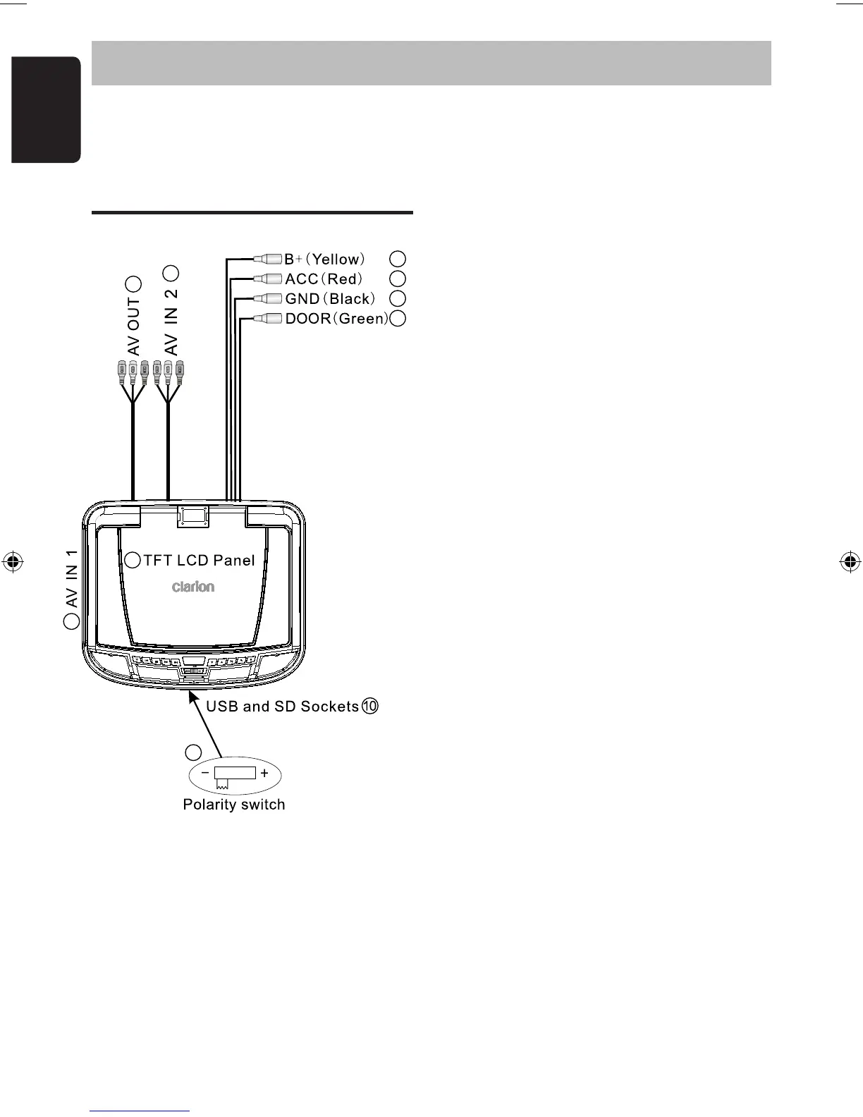
Wiring and Connections
1. Battery + Lead (Yellow)
Connect to the POSITIVE terminal of the
car battery (Fused).
2. ACC Power Lead (Red)
Connect to a current capable, switched
+ACC connection of the vehicle (Fused).
3. Ground Lead (Black)
Connect securely to a good, clean chassis
ground in the vehicle.
Ensure the connection is to bare metal.
4. Door Lead (Green)
Connect to the door sensor/switch that
controls the existing vehicle dome light.
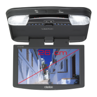
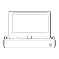
5. TFT LCD Panel
Leave the protective film on the LCD screen
until the installation is complete.
6. AUX AV Input 1
Connect to the 3.5mm AV socket on the side
of the VTM1 using the RCA lead (supplied).
Portable video devices can use this port.
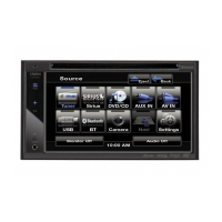
7. AUX AV Input 2
Connect to accessories installed in the vehicle
such as dash mounted video players/TV tuners
8. AUX AV Output
An auxilliary AV output for connection to
a video monitor. The audio level is not affected
by the volume setting of the VTM1.
9. Dome Light Polarity Switch
Fully slide this switch to suit the polarity (+/-)
of the vehicle dome light circuit.
IMPORTANT:
Only adjust this switch to its correct position
BEFORE connecting the Green Door Lead.
Do not adjust this switch while the VTM1 is
switched on. This may result in damage.
10. USB and SD/MMC Sockets
For use with USB Keys and SD/MMC cards
containing JPEG,. MP3 or AVI files.
Captive rubber caps help protect the
internal contacts from dirt and dust.
1
2
3
4
5
7
8
9
6