15
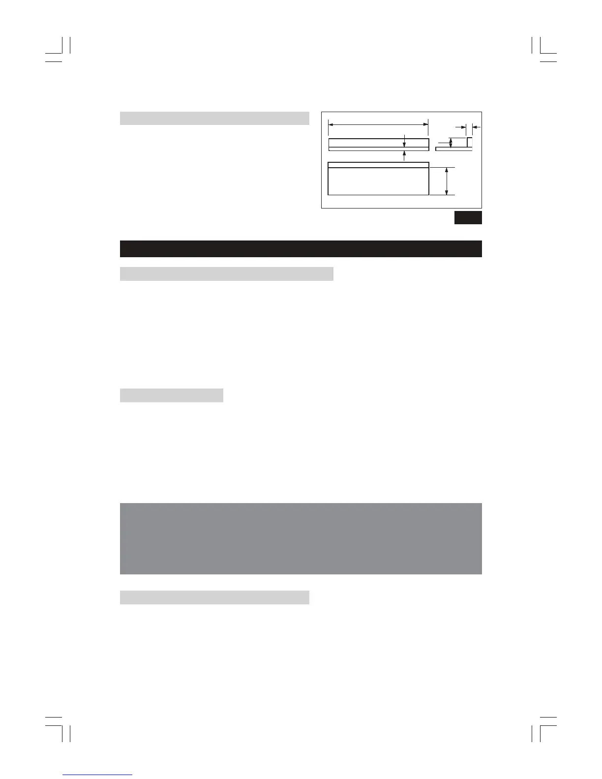
Auxiliary Fence
Make one using pieces of 10mm plywood and
19mm hardwood. Fasten together with glue
and wood screws. Dimensions are shown in Fig.
12.
NOTE:
Since the Push Block is used with the Auxiliary Fence,
the 120mm dimensions must be held identical on both
the pieces.
OPERATION
1. Starting and Stopping the Machine
The ON and OFF switches are located on the front left of the machine.
The upper, GREEN switch is the ON switch and is marked with an ‘I’ symbol.
The lower, RED switch is the OFF switch. It is raised and marked with the symbol ‘O’.
For additional safety, the ON switch is a ‘NO VOLT RELEASE’ type. This means that if the
power is interrupted for whatever reason whilst the machine is switched ON, the no volt
release will automatically trip, setting the machine to the OFF position, thereby preventing it
from starting again when the power is restored. The machine may then be restarted by
pressing the ON switch.
OVERLOAD CUT-OUT
Your machine also features an OVERLOAD CUTOUT device, so that if the machine is
overloaded (due to feed pressure being too great, a dull blade or low voltage etc.), the
overload relay will intervene and the motor will automatically cut out. In this event:
a. Press the OFF button and disconnect from the mains supply.
b. Allow the motor to cool for three to five minutes.
b. Push the reset button, which resets the overload device.
c. Plug the machine back into the mains supply, and switch the saw back on.
WARNING!
THE MACHINE MUST BE IN THE OFF POSITION, AND THE PLUG REMOVED FROM THE POWER
SOURCE WHILE THE COOL DOWN TAKES PLACE. THIS PREVENTS ACCIDENTAL STARTING
WHEN THE RESET BUTTON IS PUSHED, AS THE NO VOLT RELEASE WILL NOT HAVE TRIPPED
UNLESS THIS PROCEDURE IS ADOPTED.
2.Ripping or Rip Cutting
This is the term used for cutting timber in the same direction as the grain, i.e usually lengthwise.
To assist in producing a straight, true cut, a RIP FENCE is used. This is positioned to the right
of the saw blade, and may be adjusted to suit the width of cut required, and firmly
secured in place, ensuring it is parallel to the blade, by screwing in the rip fence handle.
DO NOT overtighten the handle as this will seriously damage the rip fence fittings.
Fig.12
445mm
44mm
10mm
Auxiliary Fence
19mm
120mm
 Loading...