23
4. Adjusting 90 and 45 Degree Positive Stops
WARNING!
ENSURE THE PLUG IS DISCONNECTED FROM THE POWER SUPPLY BEFORE PROCEEDING
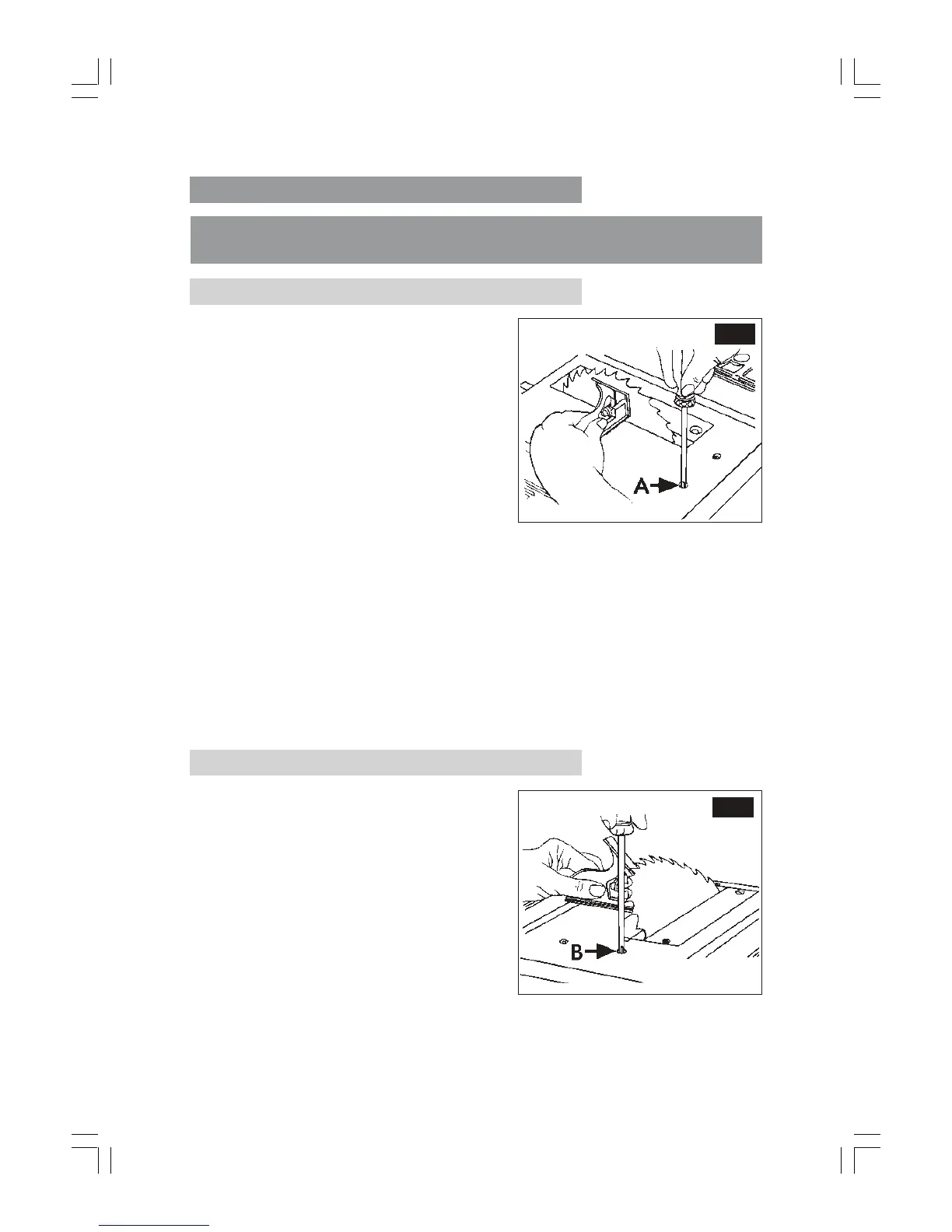
4A. Adjusting Positive Stop at 90 Degrees
(i) Raise the blade to maximum height.
(ii) Loosen the blade tilt lock handle,
push the elevation wheel to the left
as far as possible and tighten the
blade tilt locking knob.
(iii) Place a combination square on the
table with one end of square against
the blade as shown (Fig.26), and
check to see if the blade is 90
O
to the
table.
If the blade is not 90
O
to the table,
proceed as follows:
(a) If the machine is permanently mounted, remove the mounting bolts then
turn the machine on to its back.
(b) Remove the Bottom Plate secured by four screws - one in each corner.
(c) Slacken the nut securing the stop screw ‘A’ Fig 26, from beneath.
(d) Slacken the blade tilt locking knob, then screw the adjuster screw in or out,
as necessary, whilst constantly checking the angle of the blade with the
square. When you are satisfied that the blade is at 90
O,
tighten the adjuster
screw locknut.
NOTE: BEFORE replacing the bottom cover, it is prudent to check the blades’
45
O.
setting and make any
necessary adjustments as described below.
4B. Adjusting Positive Stop at 45 Degrees.
The procedure is the same as that
above, but using a 45
O
gauge, with the
blade held firmly against the 45
O
stop.
The 45
O
adjuster screw is shown at ‘B’,
Fig. 27.
When adjustments are complete, replace the bottom cover securely.
Fig.26
Fig.27
 Loading...