22
2. Changing the Blade
This procedure is explained on page 10 under ‘Assembly’.
IMPORTANT: 1. Use only Clarke Blade, Part No. 6503125.
2. Replace the blade when teeth become damaged or dull.
WARNING!
1. TO PREVENT PERSONAL INJURY, ALWAYS DISCONNECT PLUG FROM POWER SOURCE
BEFORE CHANGING BLADES.
2. TAKE GREAT CARE WHEN HANDLING SAW BLADES - THE TEETH ARE EXTREMELY
SHARP, AND CARELESSNESS CAN CAUSE SERIOUS PERSONAL INJURY
3. Adjusting Blade Parallel to the Mitre Gauge Slots
This adjustment must be maintained to ensure
accuracy and help prevent kickback. It is
factory set prior to shipping, but should be
checked periodically to guarantee the
performance of your machine. To check and
adjust, you should proceed a follows:
3.1. Raise blade as high as it will go.
3.2. Select a tooth on the rear of saw blade
that is set to the left when viewing blade
from the front of saw, and mark this
tooth with a pencil.
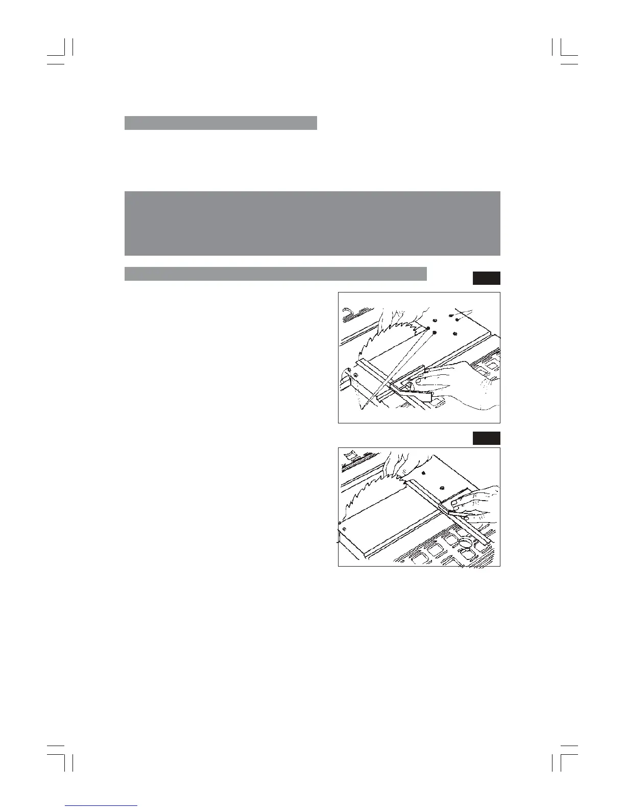
3.3 Place the base of a combination
square against the edge of the mitre
gauge slot, and extend the sliding rule
of the square so it just touches the
marked tooth (Fig.24).
3.4. Rotate blade and check the same
marked blade tooth at the front of the
saw table (Fig.25).
3.5. If measurements front and back are not
identical, proceed as follows:
a) If the machine is permanently
mounted, remove the mounting bolts
then turn the machine on to its back.
(b) Remove the Bottom Plate secured by four screws - one in each corner.
(c) Slacken the screws directly beneath the points marked at ‘A’ Fig 24, sufficient to
move the saw blade. With the machine back on its feet, align the blade so that
it is parallel to the mitre gauge slot.
(d) When the blade is correctly aligned, very carefully turn the machine on to its
back again and tighten the screws previously slackened.
If adjustment cannot be achieved by loosening the four alignment screws (A), loosen the
two secondary alignment screws located directly beneath the points marked at B, Fig. 24,
but only if it is absolutely necessary to make this adjustment.
Secondary
alignment screws (B)
Alignment screws (A)
Fig.25
Fig.24
 Loading...