CFC-E Installation Manual
Part No. 750-459 1-11
1.5.4 - Gas Piping
Do not use a common regulator to regulate gas pressure for
a multiple unit installation. Use a dedicated regulator for
each CFC-E boiler. Note: Gas connection is at the rear of
the boiler, left hand side as you face the rear of the boiler.
If local code permits, a flexible connection can be used
between the gas line and gas valve. This will enable the
burner door to be opened without disconnecting the gas
line.
The regulator for each boiler must be installed outside the
burner enclosure with at least 2 feet of pipe between the regulator and the boiler gas valve connection.
The discharge range of the regulator must be able to maintain gas pressures as noted in Model CFC-E
Gas Pressure Requirements.
A “full lock-up” type regulator and overpressure protection (e.g. relief valve) are required under the
following conditions:
CFC-E 500-2000 - with gas supply pressure exceeding 28" w.c. (14” w.c. in Canada).
CFC-E 2500-6000 - with gas supply pressure exceedig 5 psig.
Some regulators require venting to atmosphere, and certain jurisdictions allow vent limiters. Review gas
pressure regulator and relief valve installation requirements, and local code requirements.
In addition to the regulator, a plug type or “butterball” type gas shutoff valve must be installed upstream
of the regulator for use as a service valve. This is also required to provide positive shutoff and isolate the
unit during gas piping tests.
If necessary a strainer should be installed upstream of the regulator to remove debris from the gas
supply.
Drip legs are required on any vertical piping at the gas supply to each boiler so that any dirt, weld slag, or
debris can deposit in the drip leg rather than into the boiler gas train. The bottom of the drip leg should
removable without disassembling any gas piping. The connected piping to the boiler should be
supported from pipe supports and not supported by the boiler gas train or the bottom of the drip leg. Do
not pipe across the top of the boiler as the burner swings up for service and must have proper clearance.
All gas piping and components to the boiler gas train connection must comply with NFPA 54, local
codes, and utility requirements as a minimum. Only gas approved fittings, valves, or pipe should be
used. Standard industry practice for gas piping is normally Schedule 40 black iron pipe and fittings.
Before starting the unit(s) all piping must be cleaned of all debris to prevent its entrance into the boiler
gas train. Piping should be tested as noted in NFPA 54 and the boiler must be isolated during any tests.
After initial startup, the inlet screen to the gas valve should be checked and cleaned of any debris
buildup that may have resulted from installation.
A gas train leak test is recommended at installation and again at initial startup.
See Figure 1-12 for a typical piping configuration.
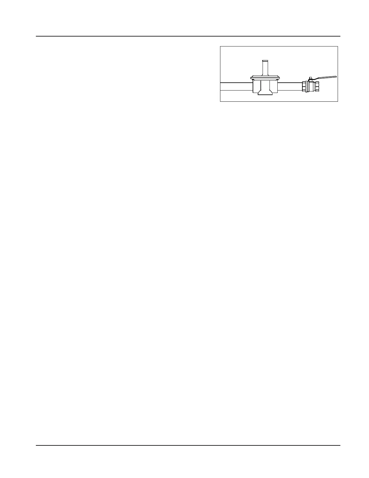
Gas Pressure Regulator
Shutoff Valve
Figure 1-10 Gas Regulator (optional)