CFC-E Installation Manual
1-20 Part No. 750-459
1.7.1 - Options
The CFC-E uses one of several condensate removal options, depending on the application:
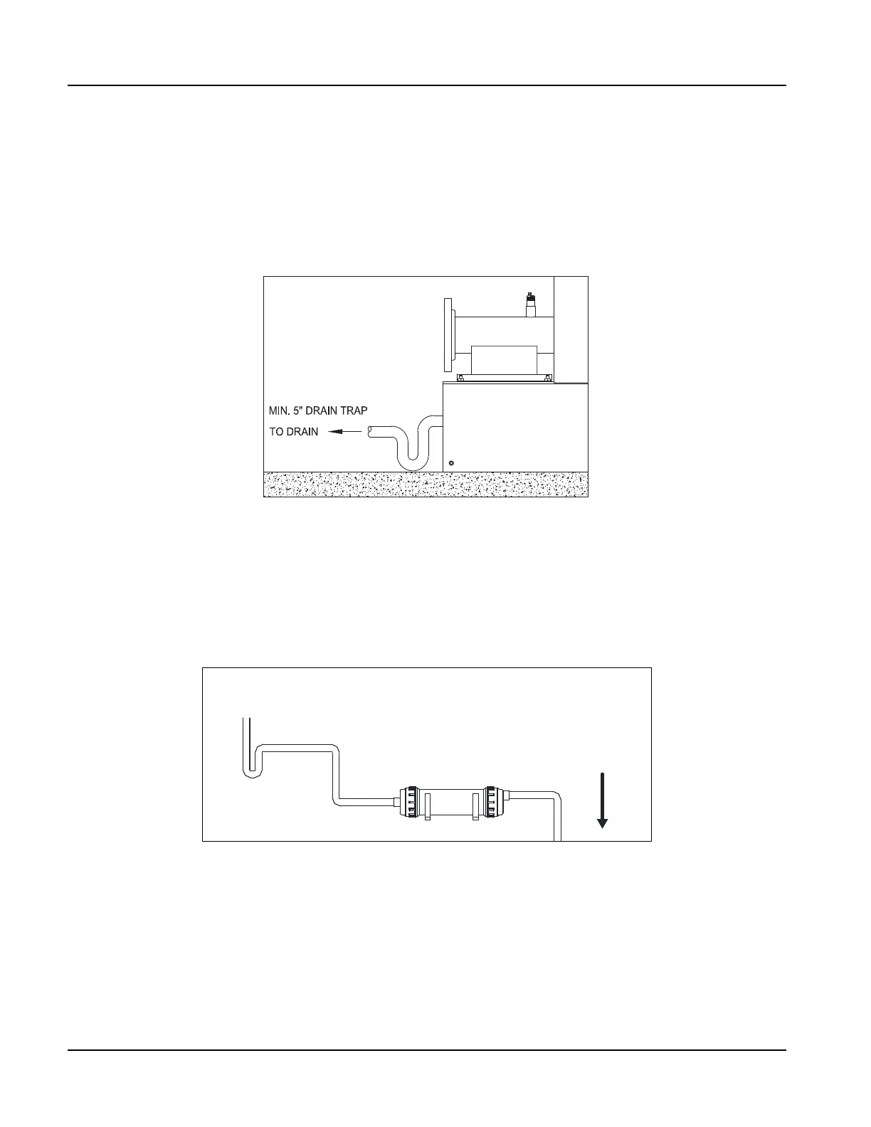
(1) Condensate direct to drain (not recommended) - The condensate is piped directly to a drain
through the piping and water trap supplied during installation (see Figure 1-16).
• Piping is to be a minimum of 3/4” NPT.
• Maximum discharge pipe height from floor to be 9”.
• Condensate water trap (5”) required.
(2) Neutralization Tube - A compact, corrosion resistant tube is piped to the condensate drain
downstream of the water trap. The tube is filled with a replaceable neutralizing agent.
The neutralization media will require periodic replacement, to be determined by pH analysis of
condensate. If condensate is too acidic (pH is below acceptable value) the neutralization media should
be replaced.
The neutralization tube option is limited to individual boilers 1000 MBH and smaller.
Figure 1-16 Neutralization Tube
(3) Combo trap/treatment tank - The condensate is held in a condensate tank near the boiler (for CFC-
E 3500-6000 boiler must be installed on a pad). The condensate is neutralized as it passes through the
granular bed. The neutralized condensate is then piped to the drain.
The combo tank features an integral water trap and float makeup valve.
• To install the system, assemble the tank and neutralization granulate per Figure 1-18. 2 bags of neutralization media are
sufficient to fill the tank.
• Connect cold make-up water at the 1/4” tube fitting.
• Install the condensate tank cover and slide the complete assembly under the boiler
Figure 1-15 Condensate direct to drain