CFC-E Installation Manual
Part No. 750-459 2-15
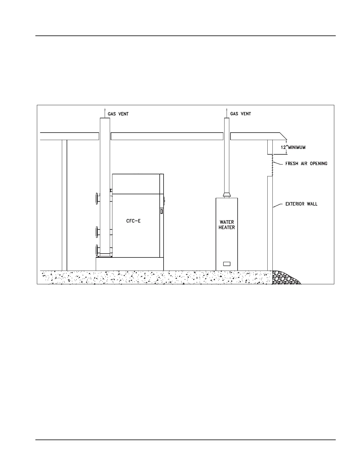
C. One Opening Method (Figure 2-9) - One permanent opening, commencing within 12 inches of
the top of the enclosure, shall be provided.
1. The equipment shall have clearances of at least 1 inch from the sides and back and 6 inches from the front of the
appliance.
2. The opening shall directly communicate with the outdoors and shall have a minimum free area of 1 square inch per
3000 BTU's per hour of the total input rating of all equipment located in the enclosure, and not less than the sum
of the areas of all vent connectors in the confined space.
3. Refer to the NFGC, Section 8.3 for additional information.
Figure 2-9 One Opening Method
2.8.2 - Air Supply - Engineered Method
When determining boiler room air requirements for an unconfined space, the size of the room, airflow,
and velocity of air must be reviewed as follows:
1. Size (area) and location of air supply openings in the boiler room.
A. Two permanent air supply openings in the outer walls of the boiler room are recommended. Locate one at
each end of the boiler room, preferably below a height of 7 feet. This allows air to sweep the length of the
boiler. See Figure 2-10.
B. Air supply openings can be louvered for weather protection, but they should not be covered with fine mesh
wire, as this type of covering has poor air flow qualities and is subject to clogging with dirt and dust.
C. A vent fan in the boiler room is not recommended, as it could create a slight vacuum under certain
conditions and cause variations in the quantity of combustion air. This can result in unsafe burner
performance.
D. Under no condition should the total area of the air supply openings be less than one square foot.