Disassembly
2 - 16 Removing the System Memory (RAM) from Under the Keyboard
2.Disassembly
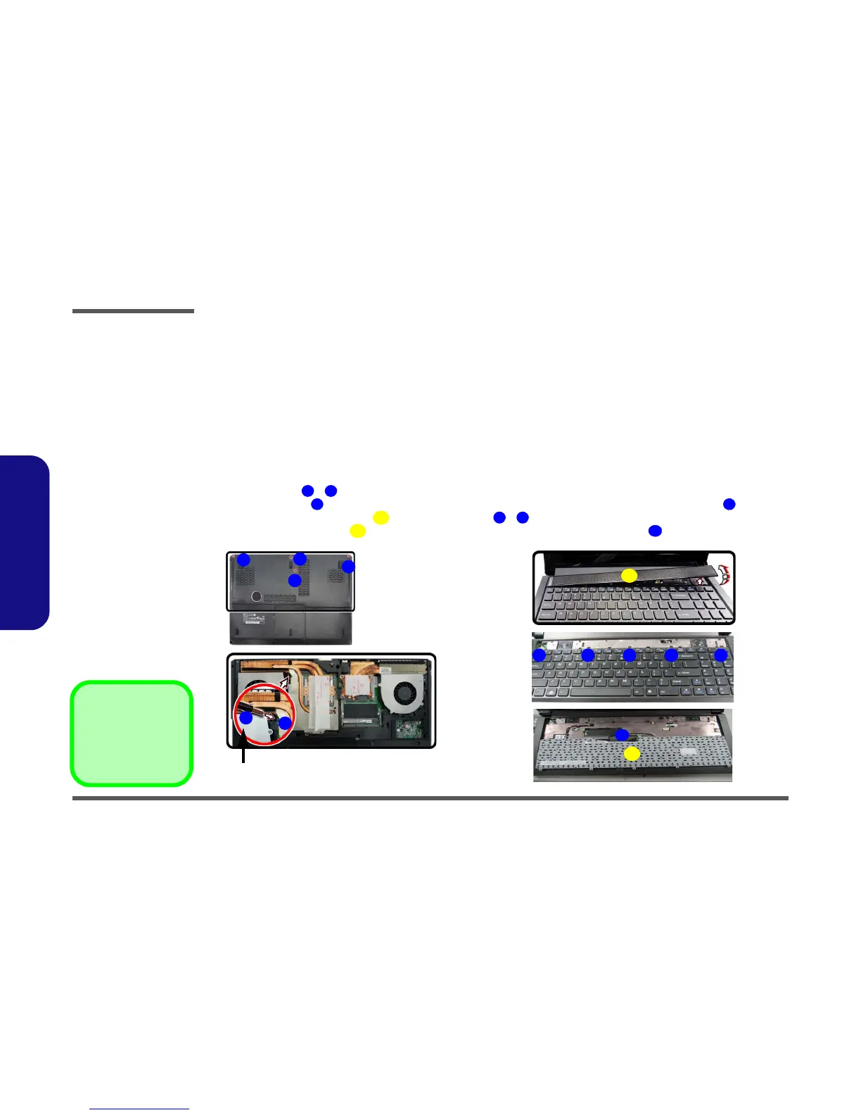
Removing the System Memory (RAM) from Under the Keyboard
The computer has four memory sockets for 204 pin Small Outline Dual In-line (SO-DIMM) DDR 3L type memory modules.
The total memory size is automatically detected by the POST routine once you turn on your computer.
Note that four SO-DIMMs are only supported by Quad-Core CPUs; Dual-Core CPUs support two SO-DIMMs maxi-
mum.
Two primary memory sockets are located under component bay cover (the bottom case cover), and two secondary
memory sockets are located under the keyboard. If you are installing only two RAM modules then they should be in-
stalled in the primary memory sockets under the component bay cover.
Memory Upgrade Process
1. Turn off the computer, and turn it over, remove the battery (page 2 - 5).
2. Remove screws - (
Figure 12a).
3. Use the small tool provided (see picture below) to carefully push out the top cover module at point .
4. Remove the top cover module and remove screws - .
5. Carefully lift the keyboard up, being careful not to bend the keyboard ribbon cable (
Figure 12e).
 Loading...