Do you have a question about the Clevo W740SU and is the answer not in the manual?
| Processor | Intel Core i7-4500U |
|---|---|
| RAM | Up to 16GB DDR3L |
| Graphics | Intel HD Graphics 4400 |
| Bluetooth | Bluetooth 4.0 |
| Webcam | HD Webcam |
| Operating System | Windows 8.1 |
| Display | 1920x1080 (Full HD) |
| Weight | 1.8 kg |
| Memory Slots | 2 |
| Audio | HD Audio |
| LAN | 10/100/1000 Mbps Ethernet |
| Card Reader | SD/MMC |
| Ports | USB 3.0, HDMI, VGA, RJ-45, Audio Jack |
| Battery | 6-Cell Smart Lithium-Ion Battery Pack 48.84WH |
Formal disclaimers about publication content, liability, and used brand names.
Describes the manual's purpose, target audience, and organization.
Essential safety precautions, care, operation, power, and battery handling guidelines.
Lists other manuals and describes initial system startup procedures.
Manual scope, notebook upgradeability, and detailed hardware specifications.
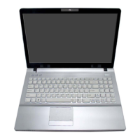
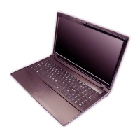
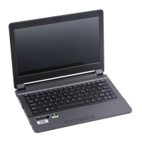
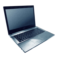
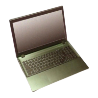
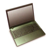
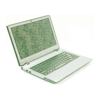
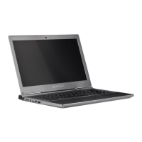
Identifies external components on the notebook's top, front, sides, and bottom.
Identifies key parts and connectors on the mainboard.
Introduces disassembly, lists tools, connector types, and safety measures.
Step-by-step instructions for removing battery, HDD, RAM, WLAN, and mSATA modules.
Table indicating where to find part list illustrations.
Part list illustrations for top/bottom assembly, HDD, and LCD.
Overall system architecture diagram illustrating major components and their connections.
Diagrams for processor interfaces, display connections, and power delivery.
Diagrams for PCH connections (SATA, USB, PCIe) and key interfaces.
Diagrams for specific components like WLAN, Audio Codec, and LAN.
Overall power distribution diagram.
Overview, download, media preparation, and boot configuration steps.
Instructions for performing the BIOS flash and restarting the computer.