16
EVH-X SPACE 2.1 - 12.1
M0SM10N17-03
5 WATER CONNECTIONS
Connection to the system
Connect the pipes to the fittings on the side of the
unit.
It is advisable to use hemp and green paste to fit
the gasket.
A unit inlet water filter is mandatory
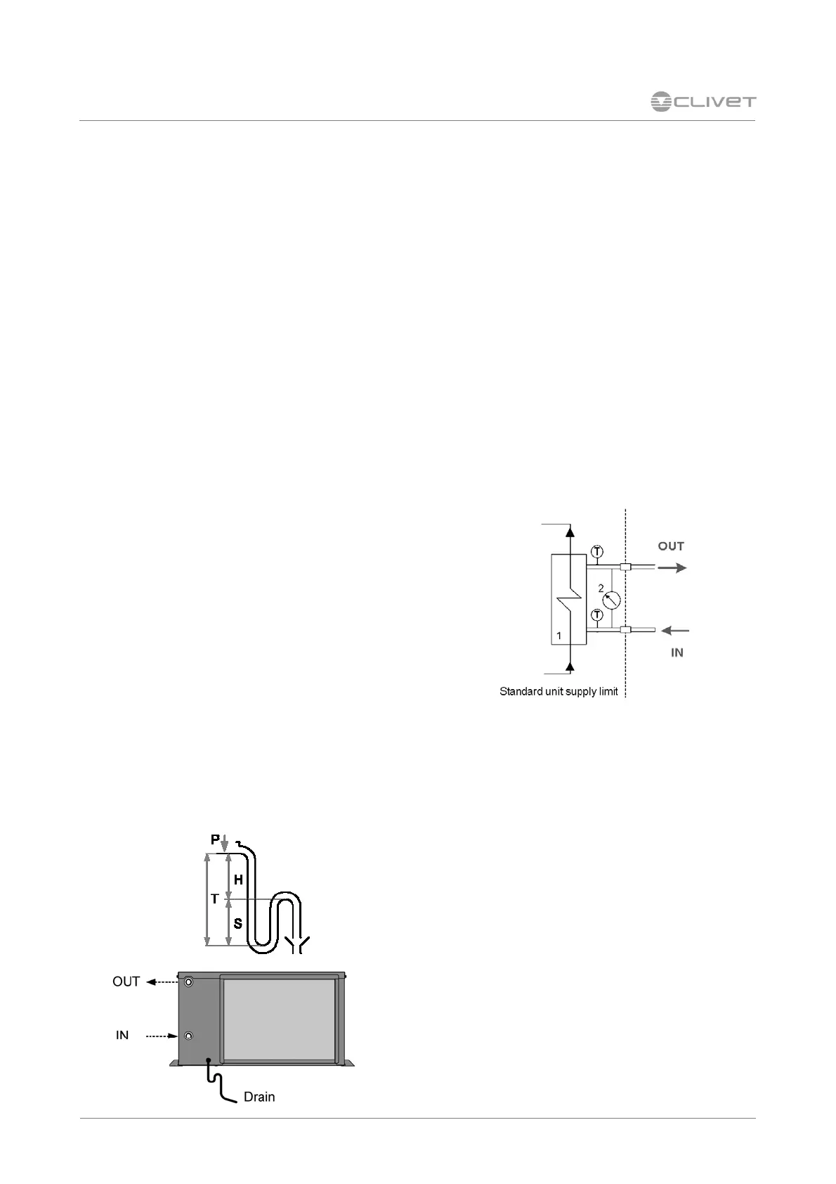
Standard hydraulic group
The standard unit includes the following
components:
1 plate exchanger and water temperature control
probes on the inlet and the outlet (to preventive
from forming and to disable the compressor
when the water temperature drops below a limit
value)
2 water side differential pressure switch (to control
the water flow rate presence)
It is compulsory the water filter on the unit
input.
Condensate discharge connection
The condensate must be disposed in order to
avoid damages to people and things.
Unit discharge fitting:
• Connect the condensate discharge to a
rainwater drain.
• the connection must avoid the transmission of
mechanical stresses and must be performed
paying attention to avoid the damaging of the
unit discharge fitting.
• Make a trap that, eliminating the depression
caused by the fan, stops the return of gas from
the discharge pipe
• Connect the condensate discharge to a
rainwater drain. Do NOT use sewerage drains,
so as to avoid the return of odours if the water
contained in the trap evaporates.
• Finally, check that the condensate will drain
correctly by pouring water into the tray stud.
• RISK OF FREEZE : If the unit operates in cooling
with external temperatures lower than 0°C, value
the possibility that the condensate can freeze
blocking the downflow and provoking flooding.
Use heat cables or other devices to guarantee
the disposal.
Siphon height calculation
T = 2P
S = T/2
P is the pressure determined by the fan in
correspondence of the condense collection bowl
(approx. 1 mm = 9.81 Pa)
Example:
P = 300 Pa = 30 mm
T = 2P = 60 mm
S = T/2 = 30 mm
 Loading...