13
Voltage
Maximum running current (A)
Wiring size (mm
2
)
220-240V~
< 0.1
2x0.75
Voltage
Maximum running current (A)
Wiring size (mm
2
)
220-240V~
1
2x0.75
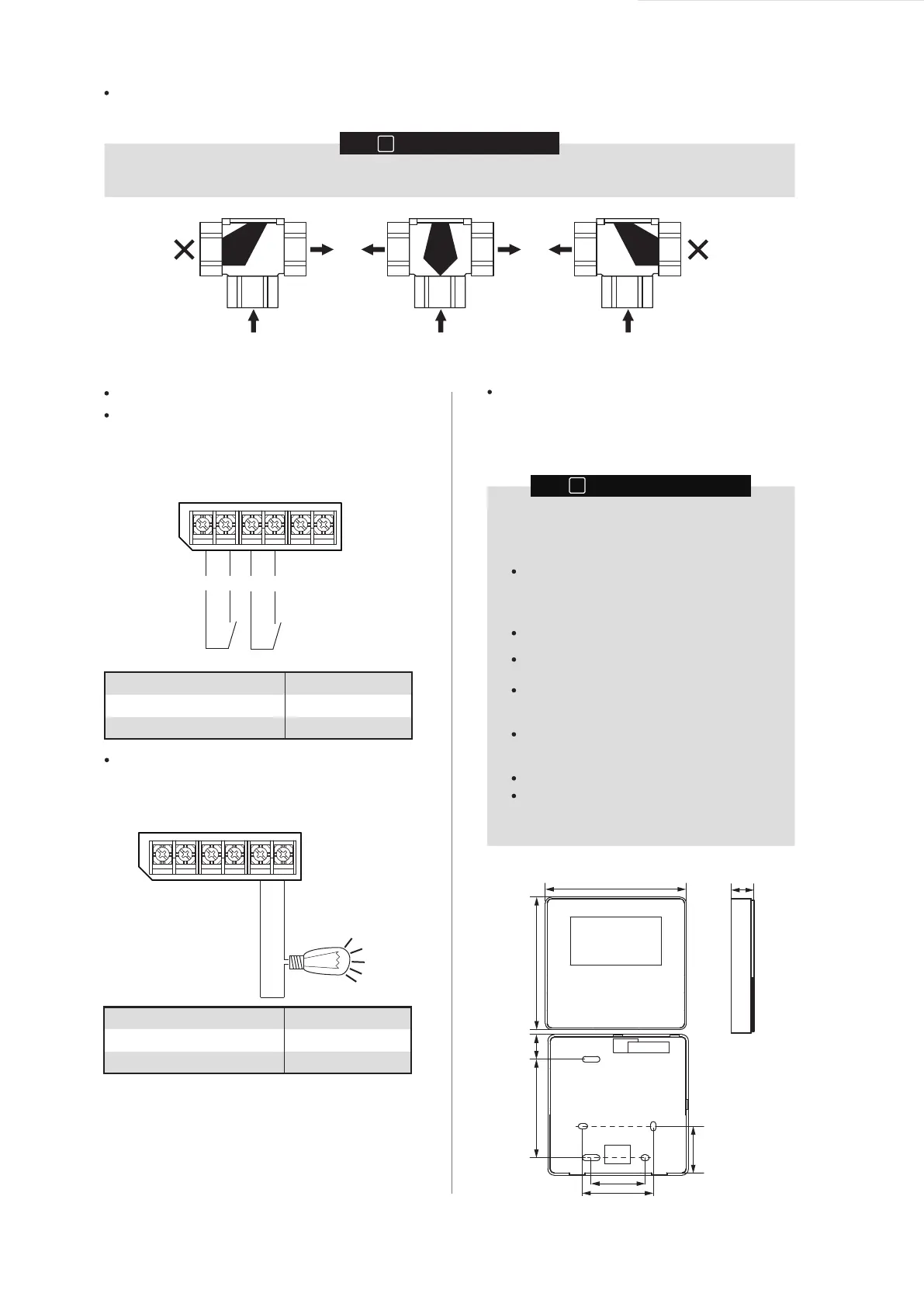
Three-way valve installation
Alarm output signal
multiple set point 1
multiple set point 2
AB
A B
AB
A B
AB
A B
Allowed (O) Not allowed (X) Allowed (O)
Check the three-way valve type. Connect it to the electric control board. For instructions on how to connect ports and wires, see page 15.
Before installing the three-way valve, check the port opening direction.
To set the temperature at multiple points, connect a
third-party thermostat to set different temperature set
points.
Installing the wired controller
When the unit fails, a signal can be output to indicate the
unit status.
CN22
N MSP1 N
N
MSP2
AL
CN22
NAL
INFORMATION
i
The connecting wire is excluded.
The wired controller is delivered as a kit and
must be installed indoors.
INFORMATION
i
This unit is equipped with a wired controller, which is
used to set, operate, and maintain this unit. Before
operating the wired controller, please follow the
installation procedures.
When the temperature control function of the
wired controller is used, please select an
installation site that satisfies the following
conditions:
The average temperature of the room can be
detected.
The installation site is free from direct
sunshine.
The installation site is not near the heat
source and the temperature is between 0 °C
and 40 °C.
The installation site is not affected by
outdoor air or air pressure, for example,
opening/closing of the door.
The display can be kept clean.
Length of commucaiton cable between hydro
module and wired controller should not be
longer than 50m.
Wired controller dimensions
120mm
120mm
20mm
19mm
84mm
46mm
60mm
44mm
 Loading...