27
Installation
2.4.6 Configuration with TWIN indoor units
POSSIBLE COMBINATIONS
TWIN indoor units are designed to be installed in one room.
The controller is used to control the main unit while the secondary unit follows the on/off, set-point, operating mode and
fan speed settings.
+
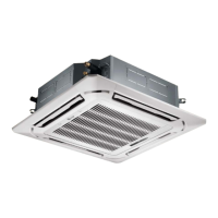
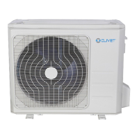
IA2-XY 70M IA2-XY 70M MC2-Y 140T
IA2-XY 105M IA2-XY 105M MC2-Y 160T
+
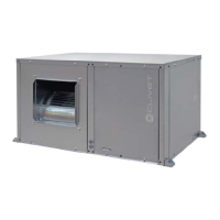
ID2-XY 70M ID2-XY 70M MC2-Y 140T
ID2-XY 105M ID2-XY 105M
+
MC2-Y 160T
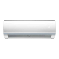
IF2-XY 70M IF2-XY 70M MC2-Y 140T
IF2-XY 105M IF2-XY 105M MC2-Y 160T
UNITÀ INTERNA 1 UNITÀ INTERNA 2 UNITÀ ESTERNA
Indoor unit 1 Indoor unit 2 Outdoor unit
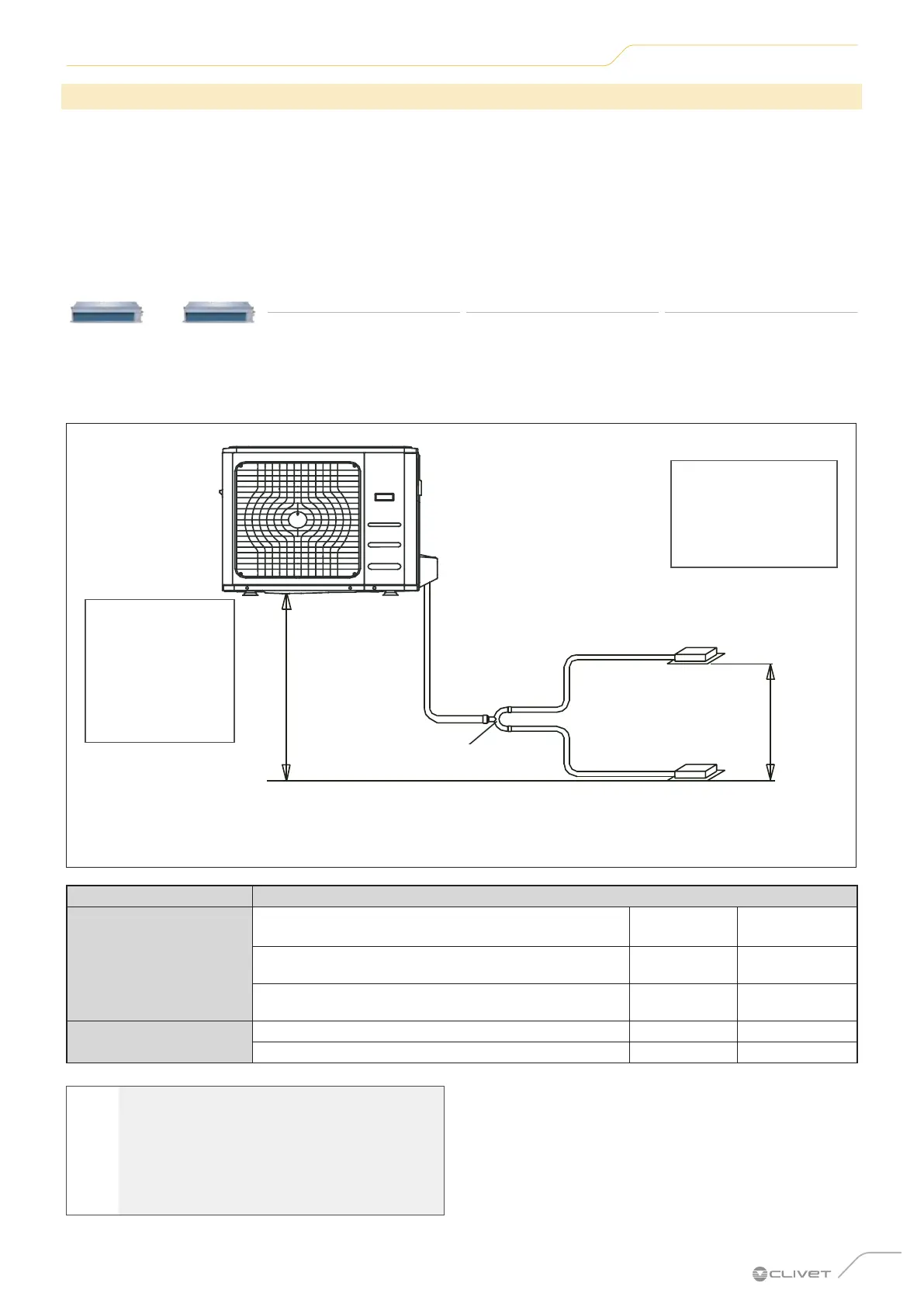
REFRIGERANT PIPING
When multiple indoor units are connected to a single outdoor unit, make sure that the length of the refrigerant pipe and
the level difference between the indoor units and the outdoor unit meet the conditions given in the diagram below:
Outdoor unit
Indoor unit
Line branching
The level difference
between two indoor
exceed 50 cm
The level
difference
between the
indoor units and
the outdoor unit
must not exceed
20 m
Indoor unit
H2
H1
L
L1
L2
Fig. 31
Length allowed
Pipe length
Total length 65m
L+Max
(L1, L2)
Max.length of single lines 15m L1, L2
Max.difference between the two L1-L2 lines 10m L1, L2
Level difference
Max.indoor-outdoor unit level difference 20m H1
Max.level difference between two indoor units 0.5m H2
l
WARNING
Make sure that the length of the refrigerant
pipe, the number of bends and the level
difference between the indoor unit and the
outdoor unit meet the requirements given in
the table.
 Loading...