28
Installation
a
CAUTION DANGER
– The Y joint must be installed horizontally.
An angle of more than 10° can cause
malfunctions.
– DO NOT install the connection pipe before
installing both the indoor and outdoor units.
– Insulate the gas side and liquid side pipes to
prevent water leaks.
10°
10°
Fig. 32
Connection pipe sizes for the indoor unit.
Model
Main pipe dimensions (mm)
Gas side Liquid side
70M Ø 15.9 mm (5/8") Ø 9.52 mm (3/8")
105M Ø 15.9 mm (5/8") Ø 9.52 mm (3/8")
Connection pipe sizes for the outdoor unit.
Based on the table below, select the diameters of the
connection pipes for the outdoor unit.
Model
Main pipe dimensions (mm)
Gas side Liquid side First Y joint
105M-105T
Ø 15.9 mm
(5/8")
Ø 9.52 mm
(3/8")
FQZHN-01D
140T
Ø 15.9 mm
(5/8")
Ø 9.52 mm
(3/8")
FQZHN-01D
160T
Ø 15.9 mm
(5/8")
Ø 9.52 mm
(3/8")
FQZHN-01D
To use the Y joint, cut the pipe following the diagram in
“Fig. 33” to fit the internal and external pipe.
ID:6.4
ID:6.4
ID:9.5
OD:9.5
OD:9.5
OD:12.7
95 ±10
Liquid pipes
Gas pipes
165 ±10
158 ±10
237 ±10
ID:9.5
ID:15.9
OD:19.1
OD:19.1
OD:19.1
ID:19.1
ID:15.9
ID:12.7
Fig. 33
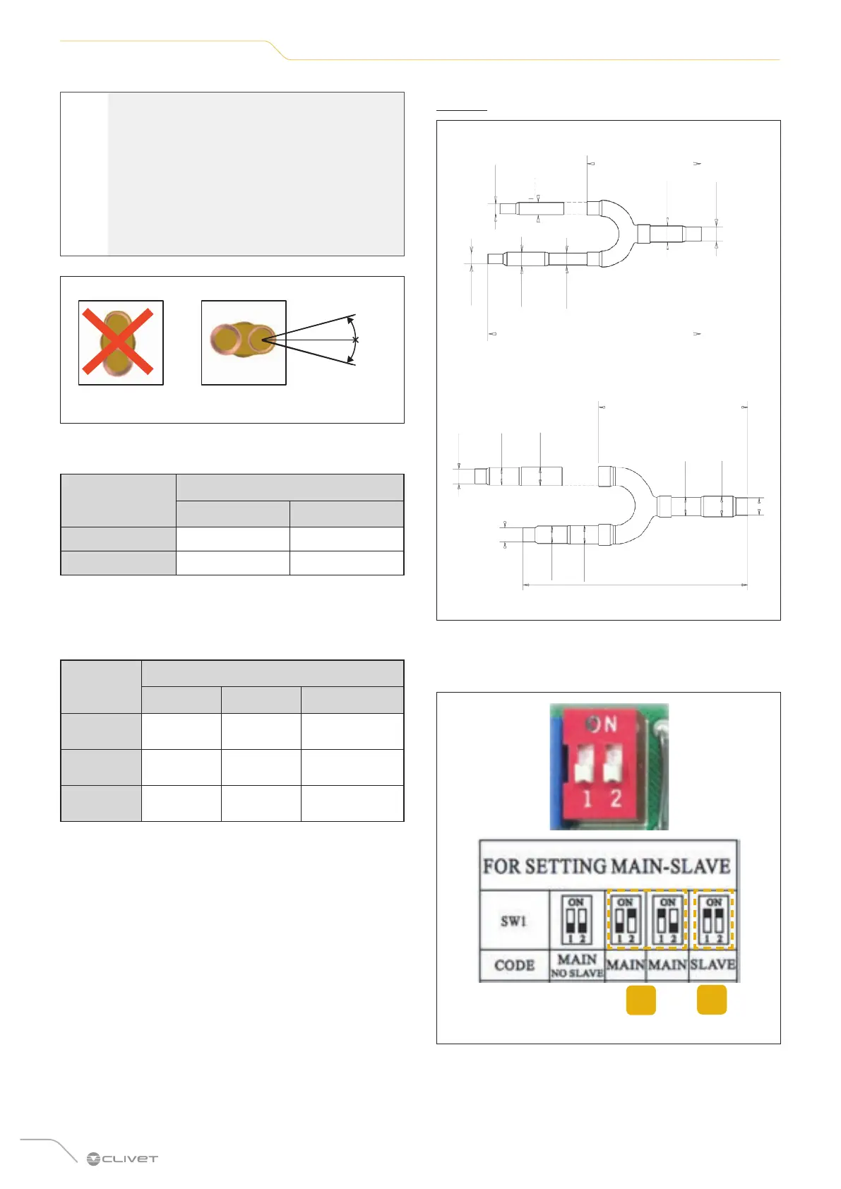
INDOOR UNIT CONFIGURATION
Set the SW1/SW5 switch
1
2
Fig. 34
1 Master indoor unit: alternate 1 and 2 (one ON and the
other OFF)
2 Slave indoor unit: both 1 and 2 ON.
 Loading...