46 Series Installation and User Guide V1.0
20
Auxiliary Outputs
46 Series mixer-ampliers are provided with two assignable
auxiliary outputs: these are available on the AUX 1 and
AUX 2 connectors
30
. These may be used to drive additional
ampliers, for recording, or any other purpose where
system “expansion” is required. The connectors are 3-pin,
3.5 mm-pitch screw terminal types.
By default, the output signals at AUX 1 and AUX 2 are
derived from the mic/music mixes for Zone 1 and Zone 2
respectively. This assignment can be changed by moving
internal jumpers J19 and/or J20. Move J19 from Z1 to Z3 to
source Aux 1 with Zone 3’s mix. Move J20 from Z2 to Z4 to
source Aux 2 with Zone 4’s mix.
It is also possible to dene whether the signals at the
auxiliary outputs are derived pre- or post-the front panel
level controls. By default, the mix is that set up for the
assigned zone by the front panel level controls (or via any of
the various remote control options). Moving internal jumpers
J21 (Aux 1) and/or J22 (Aux 2) allow the music signal to be
derived pre the zone’s music level control. This is desirable
in situations where a xed-level music signal at the auxiliary
output is required.
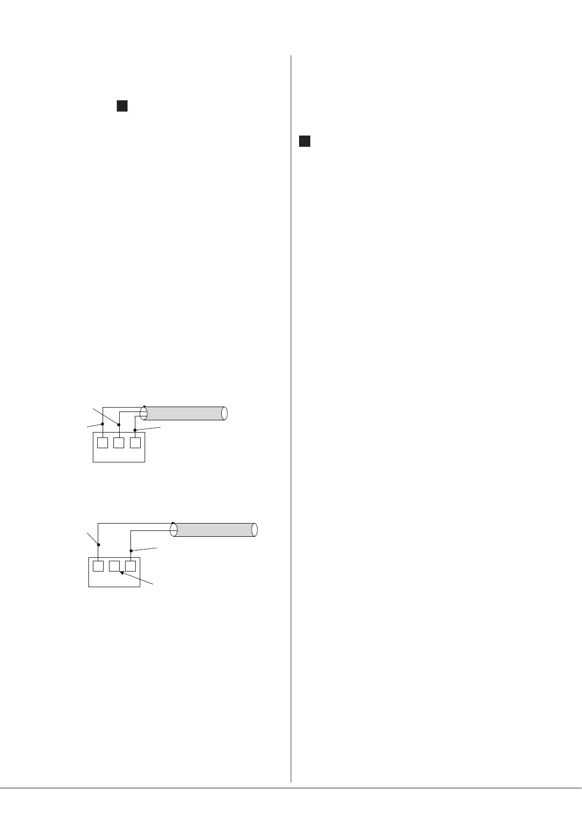
The auxiliary outputs are impedance balanced and line level,
and can thus be used to drive most external equipment
directly. The wiring is as follows:
S
+
_
AUX OUTPUT: BALANCED
CONNECTION
AUX OUTPUT: UNBALANCED
(DON’T CONNECT PIN 2)
S
+
_
scn
cold (-)
hot (+)
hot (+)
scn
Note that the signals at the auxiliary outputs are not subject
to the action of the 65 Hz high-pass lter. However, the
Mic EQ and Music EQ controls are effective on the Auxiliary
Output mix (for the mic and music components of the mix
respectively).
Utility Output
46 Series mixer-ampliers also have a Utility output, which
is ideal for providing the feed to a loop amplier, or for
connection to low-power ampliers driving speakers in
secondary areas such as corridors or toilets. It is an impedance-
balanced, line level signal available at the UTILITY connector
29
, which is a 3-pin, 3.5 mm-pitch screw-terminal type.
The Utility output can have an independent mix of music and
mic signals: the mix is adjusted with the rear panel MIC 1,
MIC 2 and MUSIC preset controls adjacent to the UTILITY
connector. By default, the music source will be that selected
for Zone 1 – either by the front panel Zone 1 SOURCE control,
or via remote control. Alternatively, the Utility output music
source may be set to be permanently that connected to Line
Input 1: this is done by moving internal jumper J23 from
Z1 to LINE1. When J23 is set to Z1 (the default), the Utility
Output will obey Line 6 Priority, if it is enabled. If J1 is set to
LINE1, it will not be affected by Line 6 Priority.
Additionally, internal jumper J24 determines whether a mic
signal (Mic 1 and/or Mic 2) at the Utility Output should cause
the selected music signal being fed to the Utility Output to
duck, the default being OFF (i.e., no ducking will occur). See
page 27 for details of PCB jumper locations.
Note also that the levels of the mic signals in the Utility
output mix are not affected by the front panel MIC LEVEL
controls.