46 Series Installation and User Guide V1.0
27
APPENDIX
PCB jumper locations
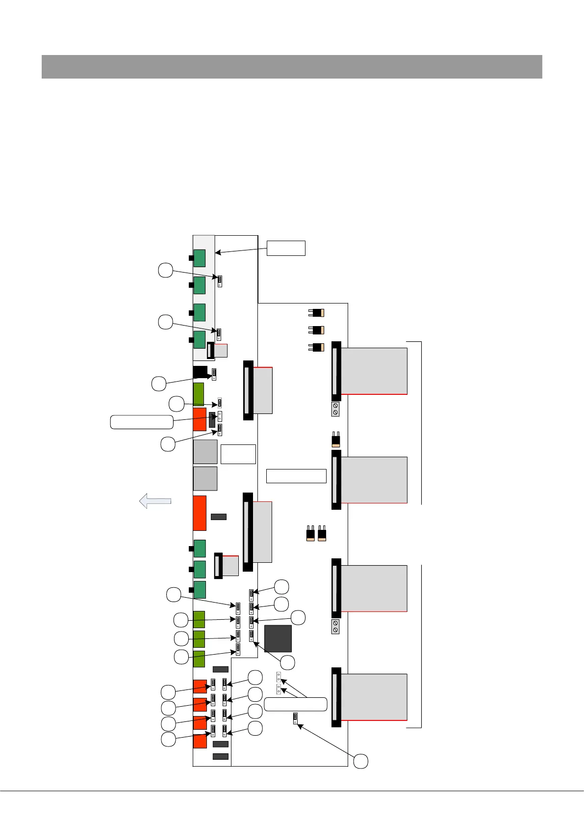
46 Series mixer-ampliers have various internal jumpers, the setting of which may require alteration during installation. The
diagram below (not to scale) shows the locations of the internal jumpers, all of which except J3, J15 and J16 are located on the
sub board mounted above the lower main PCB. J3, J15 and J16 are on the main PCB. The table below lists each jumper and its
purpose, together with the factory default setting.
All “user” jumpers have two possible positions; the black rectangle in the symbol on the diagram below indicates the default
setting. If any jumpers need to be changed, turn the unit off and disconnect it from the mains. Undo the twelve screws securing
the top cover of the unit and remove it. Use a pair of small pliers to gently remove the jumpers from the PCB headers and
reposition them as required. Ret the top cover using the same screws.
REAR OF UNIT
NOT TO SCALE
POWER MODULES &
FRONT PANEL PCB
NOT SHOWN
TO POWER/PSU
MODULES
MAIN PCB
SUB-
BOARD
J1
J2
J3
J5
J17
J25
J7
J8
J9
J10
J11
J12
J13
J18
J19
J21
J20
J22
J26
J23
J24
J6
J14:
FACTORY USE ONLY!
J15/16:
FACTORY USE ONLY!
NOTE: THERE IS NO J4
UPPER
SUB-BOARD