46 Series Installation and User Guide V1.0
23
Music Mute (Fire Alarm Interface)
In some installations (such as licensed premises or retail
outlets within a shopping mall), there may be a local authority
or re service requirement to mute the music signals from a
re alarm control panel when an alarm condition arises. 46
Series mixer-ampliers include a facility to mute the music
signals only (i.e., mic inputs are still active), via the MUSIC
MUTE input. This is a 2-pin 5 mm-pitch screw terminal
connector
31
on the rear panel.
Activation of the Music Mute is often via a relay mounted
close to the mixer-amplier, powered by the re alarm
control panel. Other arrangements may exist depending on
the design of the re control system and the alarm system
details should be consulted when making the connection. The
MUSIC MUTE input is non-isolated and connection should
only be made to isolated contacts such as on a relay or
mechanical switch. The mixer-amplier will mute the music
on either a contact closure at the Music Mute input (N/O)
or an open-circuit (N/C). Selection of N/O or N/C operation
is made with internal jumper J3. N/O is the factory default.
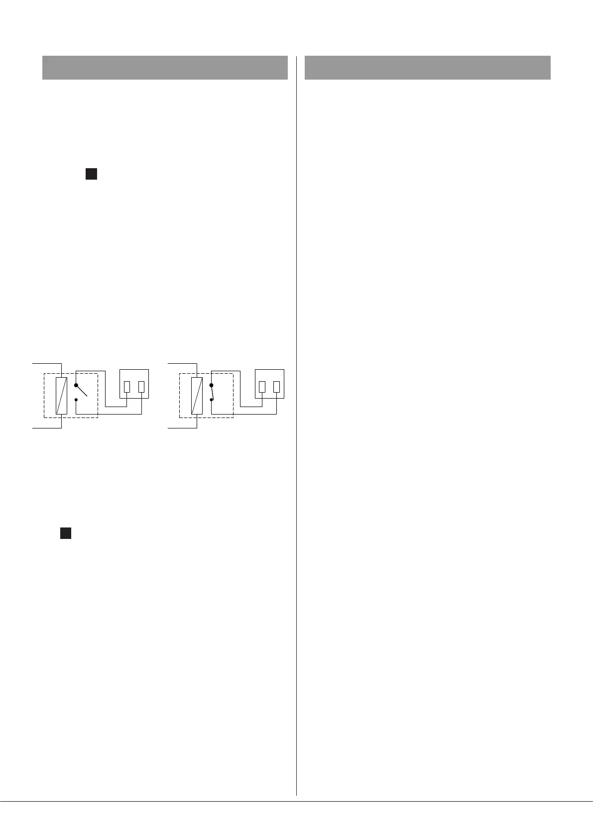
REMOTE MUSIC MUTE TERMINATIONS
1 2
MUSIC MUTE
INPUT
RELAY
NORMALLY OPEN (N/O)
CONNECTION
1 2
MUSIC MUTE
INPUT
RELAY
NORMALLY CLOSED (N/C)
CONNECTION
Note that any signal applied to a Facility Port – either from
a remote active module, or as a hard-wired direct input, will
also be muted by the action of Music Mute.
When Music Mute is active, the front panel red MUSIC MUTE
LED
7
illuminates.
Auto Power Down
A Cloud 46 Series mixer-amplier is extremely energy-
efcient, but can be made even more so by enabling the
Auto Power-Down feature. When active, the signal level
is constantly monitored and if no signals are detected at a
zone output for 15 minutes, the unit will determine whether
that channel can enter Standby mode, to minimise power
consumption. The precise behaviour differs slightly between
the two models:
• Model 46-240: each of the four zone output stages can
enter and exit Standby mode individually; signal presence
is determined solely by the monitoring of that zone.
• Model 46-120MK2: the odd- and even- zone pairs always
enter and exit Standby mode together. This means for
example, that Zone 1 and Zone 3 must both be idle before
they can be put into Standby mode, and that renewed
signal presence in either Zone 1 or Zone 3 will result in
both being “woken up”.
If a signal is detected while in Standby Mode, the unit “wakes
up” in approximately two seconds.
Units are shipped with the Auto Power Down function
disabled. It may be enabled by removing internal jumper J10.
See page 27 for location of PCB jumpers