CX263 Installation and User Guide v1.1
10
Microphone inputs
MIC 1 and MIC 2 inputs are intended for the direct
connection of microphones. They are electronically balanced
and transformerless with an input impedance of greater than
2 kohms and optimised for use with microphones of 200 to
600 ohms impedance. The screw terminal input connectors
should be wired thus:
PIN CONNECTION
1 Screen
2 Signal ‘-’ (cold)
3 Signal ‘+’ (hot)
Unbalanced microphones may be used by connecting pin 2
to pin 1 (cable screen) in the mating (male) screw-terminal
connector. 12 V phantom power is available, see “Phantom
Power” on page 13.
Each mic input may be routed to any of the zones in use,
at any level in each zone. All microphone announcements
automatically reduce the music level in that zone while the
announcement is in progress; MIC 1 input also has priority
over MIC 2 input (see “Mic-over-Music priority” on page
14 for full details.)
Zone Outputs
Connect the inputs of the power ampliers feeding the
loudspeakers for each zone to the ZONE 1 (L & R),
ZONE 2 and ZONE 3 connectors. Note that Zone 1
output is stereo, while Zones 2 and 3 are mono; Zone 1
may be recongured to operate in mono by moving internal
PCB jumper J11 (see “PCB jumper location and settings” on
page 19). The outputs are balanced and will drive input
impedances down to 600 ohms. Nominal output level is 0
dBu (775 mV). The output is designed to drive professional/
industrial power ampliers with balanced inputs (typically on
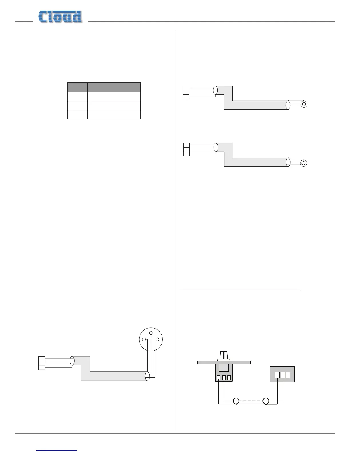
XLRs). In this case, wire as the diagram below. Note that the
screen can be left unconnected at the source end if earth
loops are a problem.
1
3
+
-
+
-
SCN
pin1ground
pin2hot
pin3cold
Balanced inputs (XLRs):
3
2
SCSCN
CX263 Balanced output:
pin 1 ground
pin 2 cold
pin 3 hot
The screen connection at the
zone end may be omitted if it
helps reduce earth loops
Ampliers with unbalanced inputs:
If audio ampliers with unbalanced inputs are being used
(e.g., hi- ampliers), the following wiring should be adopted:
1
3
+
+
2
SCSCN
pin 1 ground
pin 2 cold
pin 3 hot
When using single-core cable,
don’t connect ‘cold’ at the
CX263
Unbalanced input (e.g. phono)
1
3
+
+
-
2
SCSC N
pin 1 ground
pin 2 cold
pin 3 hot
Unbalanced input (e.g., phono)
When using twin-and-screen
cable, don’t connect the screen
at the amplifier end.
-
Music Control
Like many other Cloud products, the CX263 allows remote
control of music level and source selection in each zone.
Cloud remote control plates from the RL-1 Series (music
level only) and RSL-6 Series (music level and source selection)
provide an elegant solution, though control via a DC voltage
from third-party systems is also possible (see “Control of
music source and level via external DC” on page 15).
Both types of remote control plate connect via the REMOTE
port for the relevant zone (see [8] on “Description of rear
panel” on page 8). This connector is a 3-pin 5 mm-pitch
screw terminal type.
Connecting an RL-1 Series remote control plate
Wire the remote control plate as shown below. Either
single-core screened or twin-and-screen cable may be used;
in the case of the latter, ignore one of the cores. Maximum
reliable cable run is 100 m.
1
2
3
REMOTE
PORT
1
2
3
REMOTE LEVEL CONTROL WIRING
RL-1
SINGLE-CORE SCREENED CABLE MAY BE USED