8
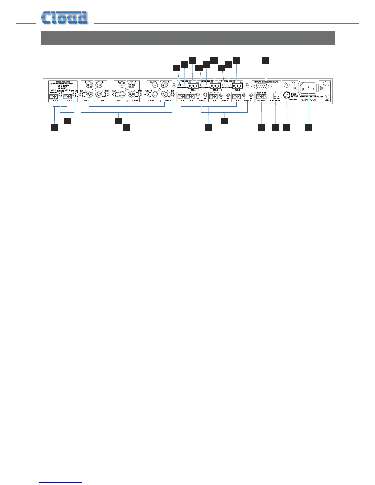
Description of rear panel
1 5 7 12 14 13
8
9
1010
9
8
10
9
8 11
2 6
3
4
1. LINE 1 to LINE 6 – six pairs of RCA (phono) sockets for connection of music sources with unbalanced outputs.
Inputs are stereo, summed internally to mono for Zones 2 and 3. See “Music Sources” on page 9.
2. GAIN 1 to GAIN 6 – gain trims for each line input.
3. MIC 1 and MIC 2 – two balanced mic inputs. Mic 1 can be used for connection of paging microphones.
See “Paging Access Control” on page 13.
4. GAIN 1 and GAIN 2 – gain trims for each mic input. See “Gain & level” on page 13.
5. OUTPUTS 1 to 3 – three balanced Zone outputs: Zone 1 is stereo, Zones 2 & 3 are mono. See “Zone Outputs” on
page 10.
6. Zone LF/HF – preset controls for EQ adjustment in each Zone. See “EQ” on page 14.
7. MIC 1 ACC – external paging control input for MIC 1. See “Paging Access Control” on page 13.
8. Z1, Z2 & Z3 REMOTE – for connection of RL-1 or RSL-6 remote control plates. See “Music Control” on page 10.
9. FR/REM – three switches disabling front panel controls for each Zone when remote control is in use.
See “Local/remote control” on page 12.
10. DIG/AN – three switches enabling operation of the optional CDI-S200 Serial Interface Card.
11. SERIAL INTERFACE CARD – optional CDI-S200 card with 9-pin Dsub connector. A blanking panel is tted when
the card is not installed.
12. MUSIC MUTE – Emergency control input for muting music source. See “Music Mute” on page 11.
13. IEC mains input
14. Mains fuse