17
Music source
Music source for a zone may be controlled by applying various DC voltages of between 0 and +10 V to pin 3, the 0 V reference
being connected to pin 1. 0 V at pin 3 will select Line input 6 and between +7.5 and +9 V will select Line input 1. The other line
inputs will be selected with intermediate voltages. Taking pin 3 above +9 V will deselect all inputs, making the zone effectively
‘off’ for music.
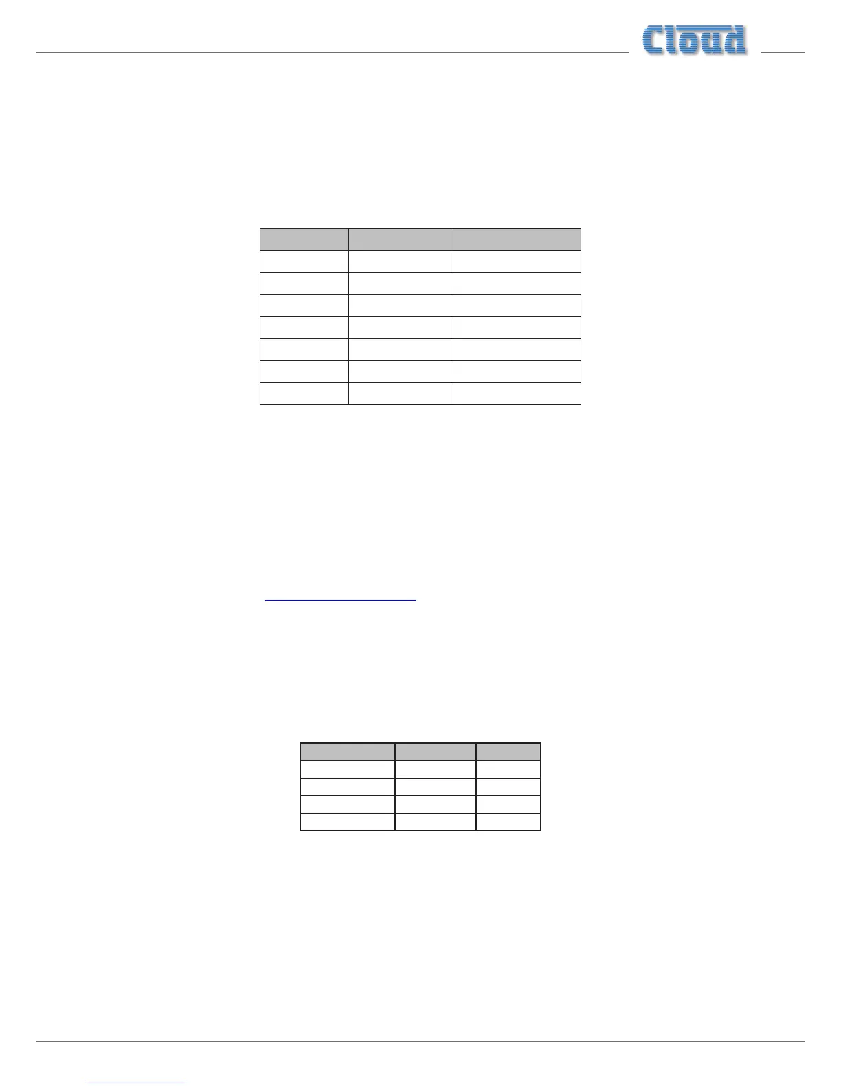
The table below lists the DC voltages required at pin 3 to select each line input. The third column is the value of a resistor which
should be connected between pins 1 and 3 to permanently ‘force’ a zone to a particular line input.
INPUT DC VOLTAGE RESISTOR VALUE
OFF >+9.0 V
Line 1 +7.5 V 16k
Line 2 +6.0 V 11k
Line 3 +4.5 V 6k8
Line 4 +3.0 V 3k9
Line 5 +1.5 V 1k8
Line 6 0 V short-circuit
Note that there is an internal 15k “pull-up” resistor between pin 3 and the internal +12 V rail. If pin 3 is left “oating”, this
pull-up will cause ‘OFF’ to be selected. The output impedance of the control voltage source should be low enough to overcome
the effect of this resistor.
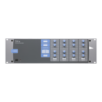
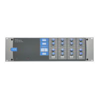
Fitting loudspeaker EQ cards
The CX263 is compatible with various popular installed-sound loudspeakers; a single-channel loudspeaker equalisation module
may be tted to any or all of the zone outputs to optimise the frequency response of the channel to the loudspeaker type being
used.
Please check the Cloud website (www.cloud.co.uk/accessories) for makes and models of loudspeakers for which EQ cards are
available.
To install equalisation modules, rst remove the top cover from the CX263 (6 screws). The modules plug into the four empty,
white 12-pin connectors in the centre of the main PCB. (Note that as Zone 1 is stereo it has two connectors.)
The connectors on the main PCB have two notches on one side only; these engage with lugs on the equalisation module’s mating
connector to ensure correct orientation. To enable the modules, an associated PCB jumper must be removed; these are listed
in the table below:
CONNECTOR ZONE JUMPER
CON3 Zone 1 Right J12
CON4 Zone 1 Left J13
CON5 Zone 2 J14
CON6 Zone 3 J15
See the Appendix section “PCB jumper locations and settings” at “PCB jumper location and settings” on page 19 for further
details. Replace the top cover with the original screws after tting.