is, the faster it will be done. If the received time window is very small, then the number of times will be reduced
to meet the window settings.
According to the test data obtained, in general, if the jumping number is 4 times, it can obtain the very
reliable detection result. That is, the noise is not a useful signal. The useful signal will be detected when
coming.
2.4 SLP Receiving Mode Detail
As mentioned above, the kernel of SLP is to control the RX time to achieve a goal. When there is usually
no useful signal, the RX time is very short and it is only used to detect the arrival of the useful signal. When
the useful signal arrives, the RX time will be extended and it can successfully receive the required packet.
So, SLP is based on the various manual, semi automatic, fully automatic RX Duty-Cycle control modes
introduced earlier, and further controls the RX status. That is, the 14 SLP patterns defined by
RX_EXTEND_MODE<3:0> are all designed to control the RX time. Except the control of the RX state,
whether it is automatic or manual, there is no necessary connection with the SLP itself, and the user can
implement different SLP modes in different RX Duty-Cycle modes.
These 14 SLP patterns are explained in detail below. First of all, we assume that CMT2300A is working in
the RX Duty-Cycle mode, automatically waking from SLEEP, automatically exiting from RX and switching to
STBY, MCU is responsible for switching from STBY to SLEEP, and switching from STBY to RX. All 13 SLP
patterns will evolve on this basis.
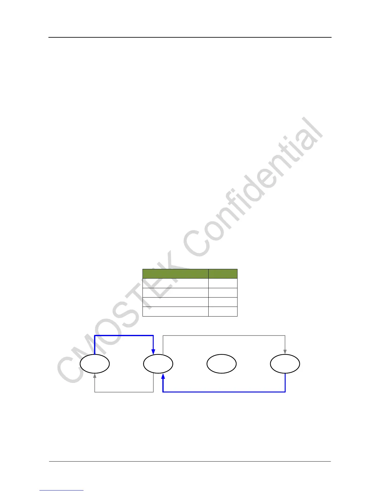
Table16. SLP Detailed Examples of the RX Duty-Cycle Mode
Figure15. SLP Detailed Examples of the RX Duty-Cycle Mode
We'll introduce the various SLP patterns based on this RX Duty-Cycle mode. The following is a summary
of the 14 patterns. The T1 and T2 mentioned in the table refer to the RX, T1, and T2 time windows that are
available in the registers.