AN146
Rev 0.9 | Page 19/25
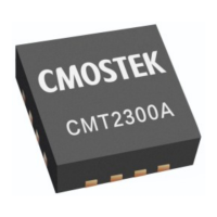
diagram below, the MCU is only responsible for sending go_rx and go_sleep command switching the status.
CMT2300A will perform to automatically wake from sleep and automatically exit from RX, and generate the
corresponding interrupt.
The time of RX and SLEEP, etc. given in the figure is only for illustration, without any special meaning.
RX T1
(30 ms)
SLEEP STBY STBY SLEEP (500 ms)
RX T1
(50 ms)
STBY STBYCAL CAL SLEEP
go_rx
RX_TMO
go_sleep go_rx go_sleep
CMT2300A
行为
MCU
控制
SL_TMO SL_TMO RX_TMO
Figure16. SLP Pattern 0
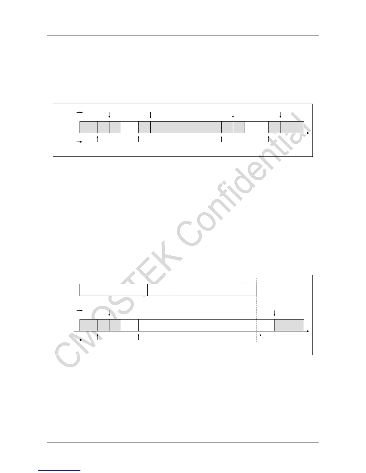
2.4.2 SLP Pattern 1~3
When the pattern is set to 1-3, once the detection condition is met within RX T1, the RX T1 will stop to
count; the chip will stay at RX and give the control to the MCU; otherwise, exit from RX after the RX T1 timer
is over. Three different conditions are as follows:
1:The detection condition is RSSI_VLD valid.
2:The detection condition is PREAM_OK valid.
3:The detection condition is RSSI_VLD and PREAM_OK valid at the same time.
Next, take option 2 as an example to give the timing diagram of TX, MCU, and RX coordination:
RX T1
(10 ms)
SLEEP STBY CAL SLEEP
go_rx
PREAM_OK有效
go_sleep
MCU
操作
Preamble Sync Word Data CRC
RX (等待MCU操作)
PKT_OK有效
TX
数据包
SL_TMO
CMT2300A
行为
Figure17. SLP Pattern 1~3
It should be noted that the preset time for RX T1 is 10ms. However, once the detection condition is met, it
will stop. For example, it stops at 7.5ms. Then it will reset and re timing when it enters the RX next time.