CNC 6040 Router / Engraver System
CNCDIY CNC Routing Machines System User’s Manual
20
3-9 Electrical Connection
The machine and the CNC control box are separated. Therefore, you need to connect each cable.
Please connect them be carefully.
3-9-1 Spindle’s Cable Connection
3-9-1-1 Pins Connecting Head of Spindle’s Cable Connection
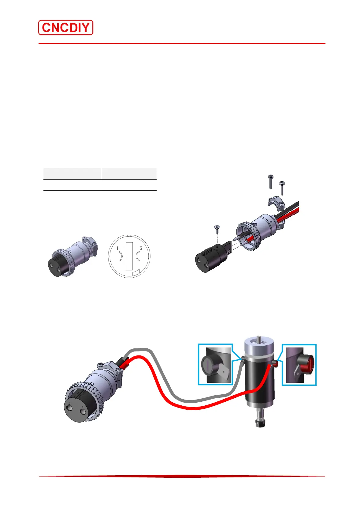
The spindle is requested two main wires, which are Cathode (+) and Anode (-) of the motor.
Therefore, you can connect them easily. The pin 1 of the 2 pins connecting head is connected to
Cathode (+) of the spindle, the pin 2 of it is connected to Anode (-) of the spindle!
Pin Number Spindle poles
1 Cathode (+)
2 Anode (-)
Outlook Welding Pins Exploded view
3-9-1-2 Spindle Connecting
The spindle has two connector for connecting the cathode (+) and the anode (-)! There are using
different colour to represent the poles of it. The red cover is Cathode (+), the black cover is
Anode (-)!
Connection diagram of spindle
Cathode (+)
Anode (-)
2 Pins Head
Cable
Spindle



 To Next Page