CNC 6040 Router / Engraver System
CNCDIY CNC Routing Machines System User’s Manual
38
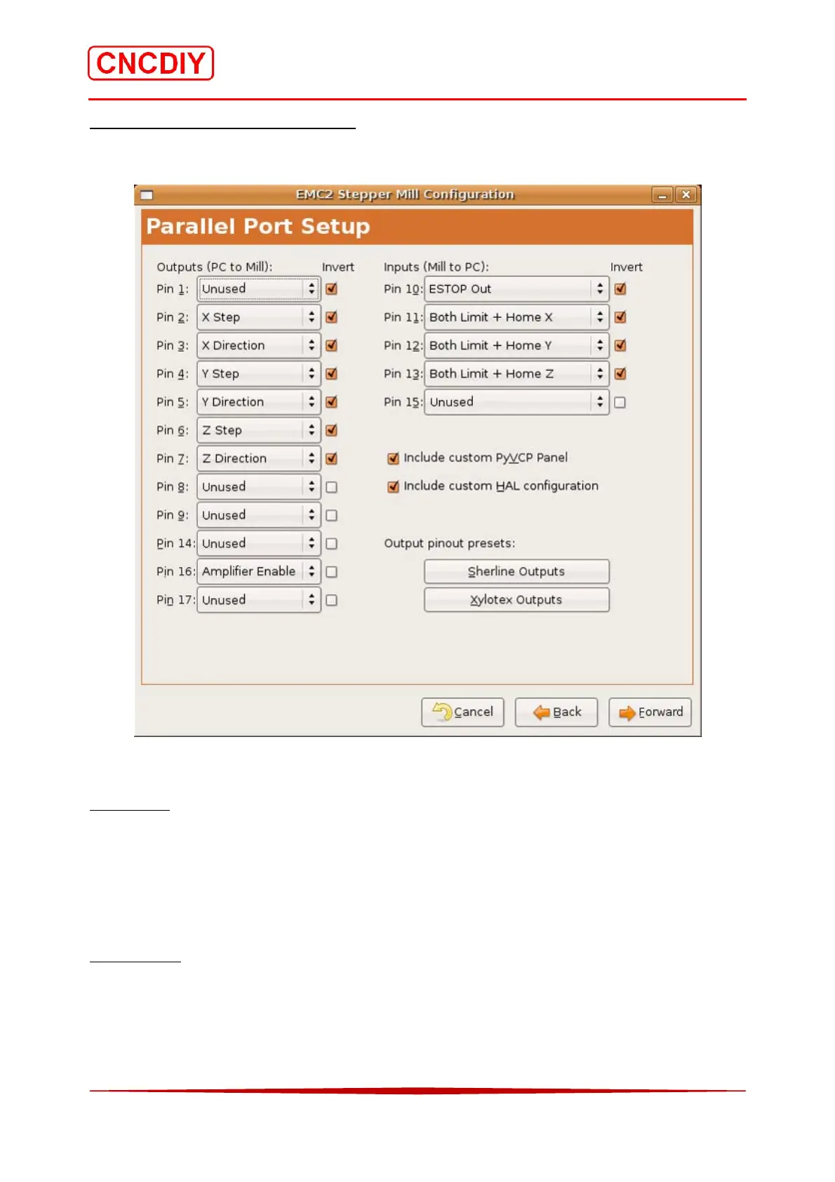
Step 5 Setting up the Parallel Port
Please follow the below setting for you parallel port! You can find the related information in the
“Parallel port interface definition” of the CNC Controller Specification:
The invert signal checkbox next to every signal is an importance functions.
Input signal
As for inputs, inversion will switch from a true signal being high (+5V) to low (0V) and a false
signal from being low (0V) to high (+5V). According to the “Parallel port interface definition” of
the CNC controller (refer to 6.1 CNC Controller Specification), the E-Stop is needed the “Active
Low input” signal, so, the invert signal checkbox of the Pin 10 (ESTOP Out) must be checked.
Output signal
On the output side inverting the signal will convert from a high (+5V) signal when active to a
low (0V signal). For example, if you find the axis direction was reversed, please change the
selection of the particular invert signal checkbox. It can be help you to select the correct
direction by software. Please refer to the chapter 3.5.4 (Understanding of direction of the axis).
 Loading...