TN855 CI-DSP-223 Telex (Vega) DSP Tone-Remote Adapter
MT-3/4 Radio Systems
TECHNICAL NOTES
Page 5 of 6
LMRSALES@CODANCOMMS.COM
CODANCOMMS.COMTECHNICAL NOTE:
TN855, REV 12-0-0, © Nov 2018
CANADA/US +1 250 382 8268 | TOLL FREE +1 800 664 4066
Telex DSP Alignment / Tuning Procedures:
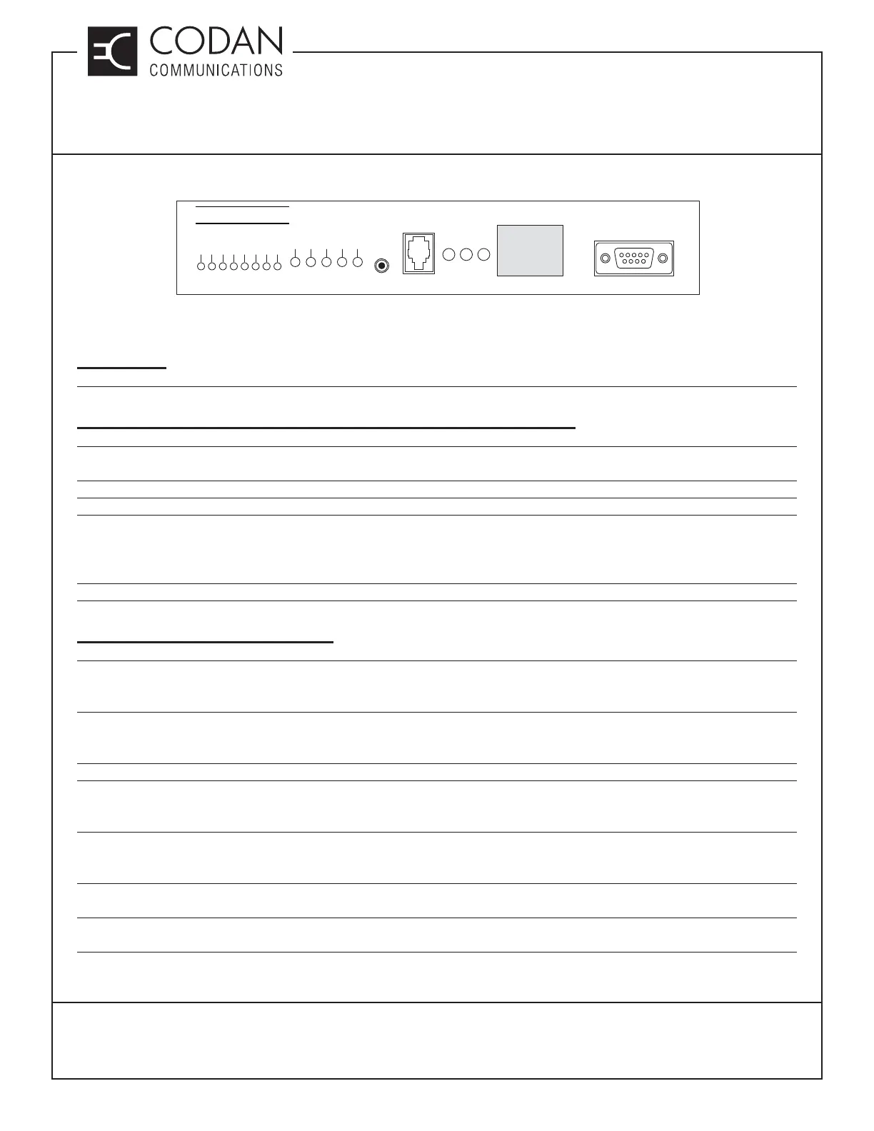
Figure 5: DSP-223 Front Panel
Initial Setup
Step 1 - Program the Telex using the Telex programming software and ensure all jumpers are correctly installed.
AC-3E Audio Control Card and CI-BC-4E Base Control Card Tuning
Step 2 - Disconnect the Telex tone remote from the Codan radio system.
Step 3 - Apply a 1.0 KHz tone @ 0 dBm (775 mV) to the GPIO 1 (Aux 1 I/P 1) and GPIO 2 (Aux 1 I/P 2) balanced
auxiliary audio input on the Codan radio system.
Step 4 - Adjust R120 (Aux In 1 to TXA) for a transmitter deviation of ± 3 KHz (WB), ± 1.5 KHz (NB).
Step 5 - Inject a 1.0 KHz tone @ a deviation of ± 3 KHz (WB), ± 1.5 KHz (NB) into Receiver A.
Step 6 - Adjust R13 (RXA to Aux Out 1) for an audio level of 0 dBm (775 mV @ 600 ohms) across GPIO 5 (Aux 1
O/P 1) and GPIO 6 (Aux 1 O/P 2) on the Codan radio system. Note: MT-4R and MT-4D P25 Receiver modules
have a higher audio level output when receiving a digital signal (as opposed to analog). When using these receiver
modules in digital mode, adjust R13 for an audio level of -8.0 dBm (308 mV @ 600 ohms).
Step 7 - Connect the Telex tone remote to the Codan radio system.
Telex Line and Radio Level Tuning
Step 8 - Using an appropriate test set (Telex C-2002), apply a 1.0 KHz tone @ 0 dBm into the tone remote.
Step 9 - On the front panel of the Telex, monitor the receive line level (AC Voltmeter across LINE RX and GROUND)
and adjust the LINE RX pot for 500 mV. This level can vary with the cable length between the console and the
remote.
Step 10 - On the front panel of the Telex, monitor the transmit radio level (AC Voltmeter across RADIO TX+ and
RADIO TX-) and adjust the RADIO TX pot for 0 dBm (775 mV) or a transmitter deviation of ± 3 KHz (WB), ± 1.5
KHz (NB).
Step 11 - Inject a 1.0 KHz tone @ a deviation of ± 3 KHz (WB), ± 1.5 KHz (NB) into Receiver A.
Step 12 - On the front panel of the Telex, monitor the receive radio level (AC Voltmeter across RADIO RX and
GROUND) and adjust the RADIO RX pot for 0 dBm (775 mV). Note: When adjusting R13 in Step 6 for an audio
level of -8.0 dBm (308 mV), adjust the RADIO RX pot for -8.0 dBm (308 mV).
Step 13 - On the front panel of the Telex, monitor the transmit line level (AC Voltmeter across LINE TX+ and LINE
TX-) and adjust the LINE TX pot for 0 dBm (775 mV). This level can vary with the cable length between the console
and the remote.
Step 14 - Set the Communications analyzer to monitor the deviation level of the transmitter CTCSS encode tone
(enable 300 Hz Lowpass fi lter).
Step 15 - Key the Telex test set with a CTCSS tone programmed and adjust the CTCSS pot on the front panel of
the Telex for a transmitter deviation of ± 500 Hz (WB), ± 350 Hz (NB).
TELEX
PROGRAMMING PORT
DSP-223
PTT IC
HANDSET
POWER PTT MONITOR
FUNCTION
CTCSS
LINE RX
LINE TX +
RADIO TX +
RADIO RX
LINE TX
LINE RX
RADIO TX
RADIO RX
CTCSS
RADIO TX -
GROUND
LINE TX -