TN856 CI-IP-223 Telex (Vega) IP Network Remote Adapter
MT-3/4 Radio Systems
TECHNICAL NOTES
Page 3 of 4
LMRSALES@CODANCOMMS.COM
CODANCOMMS.COMTECHNICAL NOTE:
TN856, REV 7-0-0, © Aug 2016
CANADA/US +1 250 382 8268 | TOLL FREE +1 800 664 4066
Telex IP Alignment / Tuning Procedures:
Initial Setup
Step 1 - Program the Telex and ensure all jumpers are correctly installed.
AC-3E Audio Control Card and CI-BC-4E Base Control Card Tuning
Step 2 - Disconnect the Telex from the Codan radio system.
Step 3 - Apply a 1.0 KHz tone @ 0 dBm (775 mV) to the GPIO 1 (Aux1 I/P 1) and GPIO 2 (Aux1 I/P 2) balanced
auxiliary audio input on the Codan radio system.
Step 4 - Adjust R120 (Aux In 1 to TXA) for a transmitter deviation of ± 3 KHz (WB), ± 1.5 KHz (NB).
Step 5 - Inject a 1.0 KHz tone @ a deviation of ± 3 KHz (WB), ± 1.5 KHz (NB) into Receiver A.
Step 6 - Adjust R13 (RXA to Aux Out 1) for an audio level of 0 dBm (775 mV @ 600 ohms) across GPIO 5 (Aux 1
O/P 1) and GPIO 6 (Aux 1 O/P 2) on the Codan radio system. Note: MT-4R and MT-4D P25 Receiver modules
have a higher audio level output when receiving a digital signal (as opposed to analog). When using these receiver
modules in digital mode, adjust R13 for an audio level of -8.0 dBm (308 mV @ 600 ohms).
Step 7 - Connect the Telex to the Codan radio system.
Vega Line and Radio Level Tuning
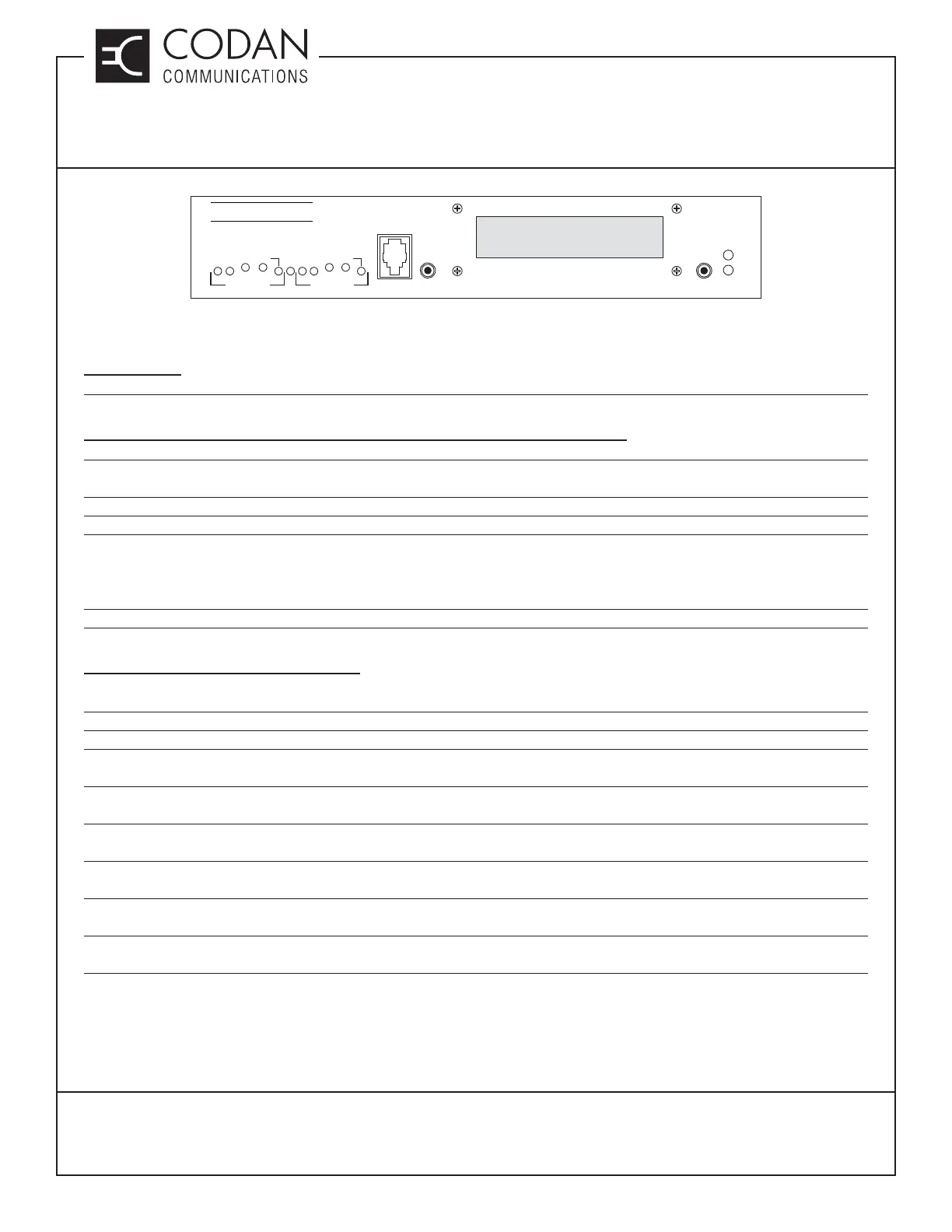
Step 8 - Press and hold the LINE button on the front of the Telex and triple click the IC button so that “VU1 -50db /
VU2 -50db” is displayed on the LCD display.
Step 9 - Inject a 1.0 KHz tone @ a deviation of ± 3 KHz (WB), ± 1.5 KHz (NB) into Receiver A.
Step 10 - Adjust the RX pot until VU1 reads 0.0 db.
Step 11 - Press and hold the LINE button on the front of the Telex and click the IC button to return to normal
operation.
Step 12 - Press and hold the LINE button on the front of the Telex and double click the IC button so that “Tx Align”
is displayed on the LCD display.
Step 13 - Key the Codan transmitter and adjust the TX pot for a transmitter deviation of ± 3 KHz (WB), ± 1.5 KHz
(NB).
Step 14 - Press and hold the LINE button on the front of the Telex and double click the IC button to return to normal
operation.
Step 15 - Set the Communications analyzer to monitor the deviation level of the transmitter CTCSS encode tone
(enable 300 Hz Lowpass fi lter).
Step 16 - Key the Telex test set with a CTCSS tone programmed and adjust the CTCSS LINE 1 pot on the top of
the Telex for a transmitter deviation of ± 500 Hz (WB), ± 350 Hz (NB).
IP-223
TX
LNK
LINE
HANDSET
RX
GND
TX+
IC
TX-
TX
RX
TX
TX+
TX-
RADIO 1 RADIO 2
TELEX