TN735 ET-6 Transportable Tactical Radio System
MT-3/4 Radio Systems
TECHNICAL NOTES
Page 3 of 4
LMRSALES@CODANCOMMS.COM
CODANCOMMS.COMTECHNICAL NOTE:
TN735, REV 4-0-0, © Aug 2016
CANADA/US +1 250 382 8268 | TOLL FREE +1 800 664 4066
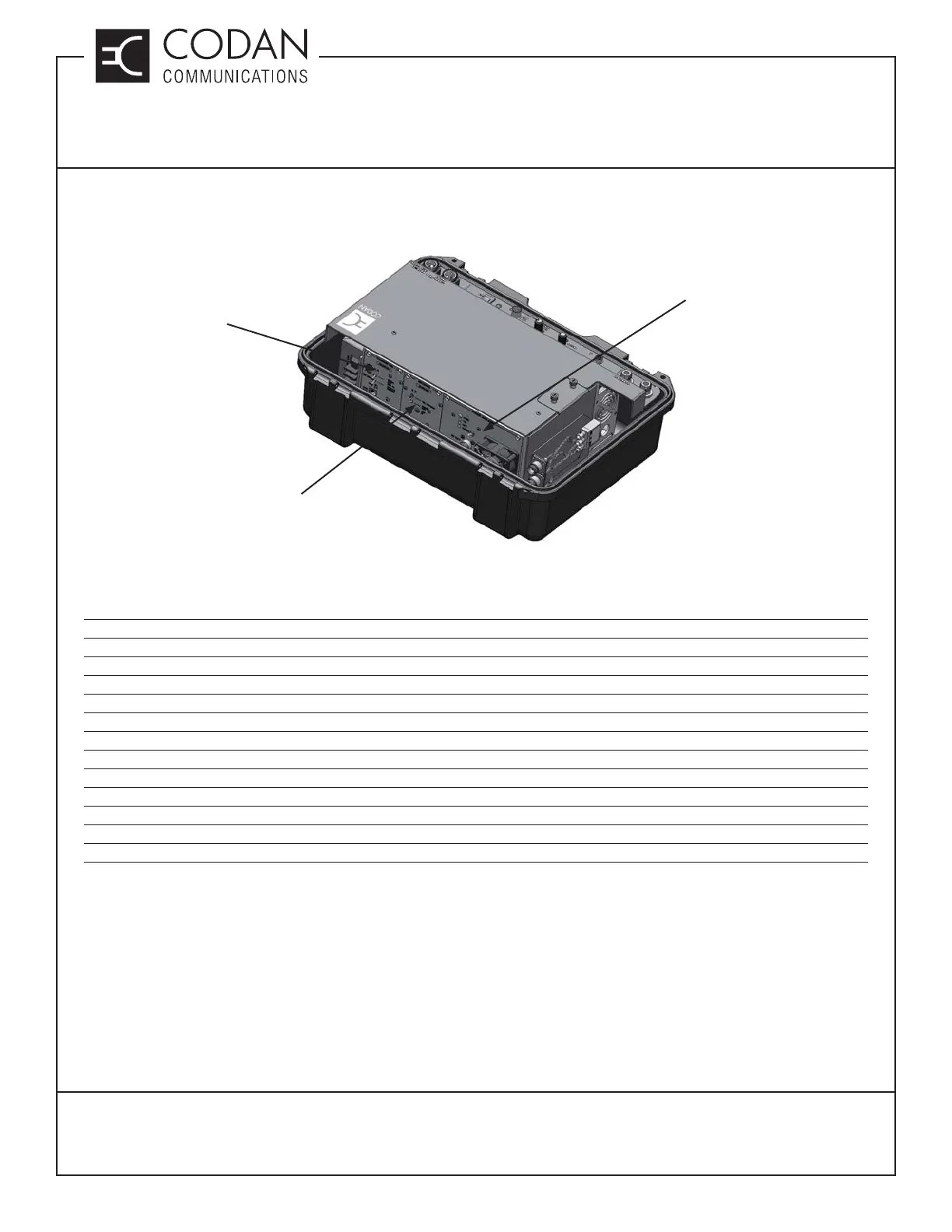
The ET-6 case with the lid removed is shown in Figure 1. This shows how the receiver, transmitter and power
amplifi er are mounted inside of the ET-6 case.
Figure 1: ET-6 case with case lid removed
The DB25 auxiliary connector pinout is as follows:
Pin Function Notes
7 Ground
8 Transmitter CSEL0 Jumper JU5A installed to operate
9 Transmitter CSEL2 Jumper JU5A installed to operate
12 Receiver Balanced O/P 2
13 Transmitter Balanced I/P 2
14 Transmitter PTT I/P
17 Transmitter Secure / Clear I/P Pull to ground for Clear mode
20 +13.8 Vdc / Receiver COR Jumper JU1A (DSP-223) / Jumper JU1B (IP-223 / IP-224)
21 Transmitter CSEL1 Jumper JU5A installed to operate
22 Transmitter CSEL3 Jumper JU5A installed to operate
24 Receiver Balanced O/P 1
25 Transmitter Balanced I/P 1
The IP-223 / IP-224 also requires that 2 pins on the DB25 (PTT COM - pin2 and MON COM - pin 16) are wired to
ground for proper operation.
30 WATT POWER
AMPLIFIER
RECEIVER
TRANSMITTER