Code Blue
• 259 Hedcor Street • Holland, MI 49423 USA • 800.205.7186 • www.codeblue.com
page 16 of 43 GU-149-DD
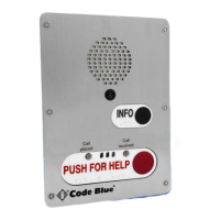
CB 2 Series
Administrator Guide
CB 2-s Installation Instructions
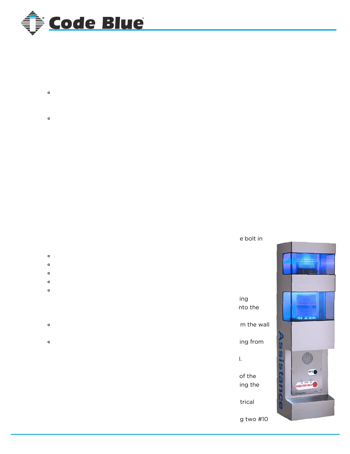
1. Unscrew security screw from top of unit. Lift and open unit.
2. Open or remove the unit shell.
Open: Allow top of shell to fall open while base of the shell remains in
contact with base of backplate. Unit will prop open to the length of the
safety cable so you can continue hands-free installation of the unit.
Remove: Allow unit shell to fall open to the length of the safety cable.
Unplug the area light and strobe light, and disconnect the safety cable to
fully detach the front face. Set aside for easier access to mounting holes.
3. Using a level and measuring tape, mark the appropriate height and mounting
hole placement by referring to the wall mounting diagram on page 8, or holding
the the unit against the wall as a template.
4. Using a 3/8” drill bit , drill the pilot holes
5. Insert anchors into pilot holes. (For concrete walls only: If mounting to wood
wall, skip this step)
6. Pre-assemble bolts into unit mounting holes with washers placed on the bolt in
order of:
Steel washer
Rubber washer
Unit backplate
Rubber washer
Steel washer
7. Holes in the back and bottom of the unit have been provided for running
conduit. If conduit is prepared, lift the unit up to the wall and run wires into the
unit:
through the two backplate conduit holes (if conduit is coming from the wall
behind), or
through the two bottom conduit holes (if conduit is external coming from
below the unit).
8. Using a 3/8 drill bit or ratchet, secure the bolts to affix unit to the wall.
9. Reattach Light Bracket.
10. Reattach the outer shell: Holding the shell perpendicular to the base of the
backplate, hook the bottom hinge into the bottom of the back plate. Swing the
shell up and fasten the safety cable to the eyehook.
11. While the unit shell is propped open on the safety cable, connect electrical
wiring to incoming power supply
12. Push the shell closed and fasten the outer shell to the back plate using two #10
countersunk security screws.
NOTE: In order to comply with the Americans with Disabilities Act (ADA) of
1990, the speakerphone button(s) should be positioned between 34 and 48
inches from grade level. (Consult an ADA specialist in your area to verify local
and federal guidelines.)